ECM-S12-24: Difference between revisions
| (39 intermediate revisions by 6 users not shown) | |||
| Line 2: | Line 2: | ||
<gallery> | <gallery> | ||
File:ECM-S12-24.jpg| | File:ECM-S12-24.jpg|ECM-S12-24 | ||
</gallery> | </gallery> | ||
===Product Summary=== | ===Product Summary=== | ||
These rugged embedded controllers are capable of operating in harsh automotive, marine | These rugged embedded controllers are capable of operating in harsh automotive, marine and off-highway applications. Hundreds of successful industrial applications prove the capability of this module. Based on a proven microprocessor, it is capable of delivering complex control strategies. The CAN 2.0B datalink ensures interoperability with other system components. | ||
:'''Features include:''' | :'''Features include:''' | ||
::*Freescale MC9S12DT128, 24MHz Microprocessor | ::*Freescale MC9S12DT128, 24MHz Microprocessor | ||
::*Operating Voltage: 8- | ::*Operating Voltage: 8-20VDC | ||
::*Operating temperature ranging between -40°C to 105°C | ::*Operating temperature ranging between -40°C to 105°C | ||
::*Sealed connectors | ::*Sealed connectors operable to 10 ft submerged | ||
:'''Family includes:''' | :'''Family includes:''' | ||
| Line 20: | Line 20: | ||
::*ECM-S12-24-0803 | ::*ECM-S12-24-0803 | ||
::*ECM-S12-24-0804 | ::*ECM-S12-24-0804 | ||
===Datasheets=== | ===<div style="font-size:21px; width:75%; font-weight:bold; text-align:left; padding-top:7px; padding-bottom:7px; background:#800020; color:white;">Datasheets</div>=== | ||
'''[ | '''ECM-0S12-024-0801''' & '''ECM-0S12-024-0804''' | ||
:'''[http://Neweagle.net/support/wiki/ProductDocumentation/Controllers/ECM-0S12-024/ECM-0S12-024-0804_DataSheet.pdf Datasheet]''' | |||
'''ECM-0S12-024-0802''' | |||
:'''[http://Neweagle.net/support/wiki/ProductDocumentation/Controllers/ECM-0S12-024/ECM_S12-024-0802_DataSheet.pdf Datasheet]''' | |||
== | == Frequently Asked Questions (FAQ) == | ||
{{24 PIN Family FAQ}} | {{24 PIN Family FAQ}} | ||
| Line 42: | Line 45: | ||
::*Likewise, the SECM0803 is a "made" part, created from an SECM0801 module with that same customer-specific hardboot loader. | ::*Likewise, the SECM0803 is a "made" part, created from an SECM0801 module with that same customer-specific hardboot loader. | ||
=== Notes on the ECM-S12-24 | === Notes on the ECM-S12-24 Part Number Migration=== | ||
There | There are different software hardboots installed on the devices, but the physical hardware is identical. | ||
SECM0801 (SECM0503) | {| class = "wikitable" style = "text-align:center;" cellpadding="5" | ||
!scope="col" style = "width:180px;"|Device | |||
!scope="col" style = "width:170px;"|Hardboot | |||
!scope="col" style = "width:130px;"|City ID | |||
|- | |||
|SECM0801 (SECM0503) | |||
|"HB V1P2" | |||
|129 = 0x81 | |||
|- | |||
|SECM0804 | |||
|"HB_4_3_RC1_PROD" | |||
|11 = 0x0B | |||
|} | |||
The reason for the OEM part number changes, as from SECM0503 to SECM0801, is typically due to changing internal components (such as replacing a transistor that is end-of-life with a new, equivalent transistor) or similar issue. However, externally visible functionality is expected to be the same: i.e., the new OEM has the same ADC pull-up values, same input/output capabilities, etc. | |||
Thus, the inputs/outputs are the same for SECM0503/SECM0801 and SECM0804. | |||
We have Woodward part numbers for all products, but please work with the quotes team to make sure you get what you need. Of course, the tech support team can help, as required. | |||
===Difference Between ECM0801 and ECM0802=== | |||
The 0801 is a variation of the 0802 with different pull up/pull down combinations for the analog ins and three ESTs have been replaced by more analog ins. | |||
=== | ===CAN Bus Limitations=== | ||
The | The S12 modules do not support 1000K baud CAN bus speeds; they are hardware limited. | ||
=== VR | === VR Signal Limits === | ||
The VR input | The VR input maximum is 400v pp. | ||
=== VR | === VR Circuit === | ||
The VR circuit is built upon the LM1815M integrated circuit. http://www.ti.com/lit/ds/symlink/lm1815.pdf. | The VR circuit is built upon the LM1815M integrated circuit. See the LM1815M's datasheet '''[http://www.ti.com/lit/ds/symlink/lm1815.pdf here]'''. | ||
===Working with the S12 MotoHawk Application Document=== | ===Working with the S12 MotoHawk Application Document=== | ||
Registered wiki users can download the "Working with the S12" application help. Understanding this document is imperative for using the S12 based MotoHawk modules. | Registered wiki users can download the "Working with the S12" application help. Understanding this document is imperative for using the S12-based MotoHawk modules. The document can be found '''[[MotoHawk_Resource_Documents|here]]'''. | ||
===S12(X) Recommended Stack Size=== | |||
The '''[[MotoHawk_Resource_Documents|"Working with the S12"]]''' application document indicates a stack baseline when starting your application. Below is another recommended stack size if the stack baseline is low in certain areas. | |||
'''NOTE:''' The following stack sizes are recommendations and should be adjusted according to the application requirements. | |||
[[File:S12_stack.png]] | |||
==Other Engine Control Modules== | |||
'''[[Controllers | Engine Control Modules]]''' | |||
== Webstore == | == Webstore == | ||
'''[ | '''[https://store.neweagle.net/shop/products/controllers/motohawk-controllers/ecm-engine-control-modules/0s12-24-0802-flash-engine-control-module/ ECM-0S12-024-0802-F-M]''' | ||
'''[https://store.neweagle.net/shop/products/controllers/motohawk-controllers/ecm-engine-control-modules/0s12-24-0804-flash-engine-control-module/ ECM-0S12-024-0804-F-M]''' | |||
'''[https://store.neweagle.net/product-category/products-by-category/controllers/ All Control Modules]''' | |||
[[Category:Controllers]] | [[Category:Controllers]] | ||
Latest revision as of 14:52, 15 February 2023
ECM-S12-24
-
ECM-S12-24
Product Summary
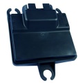
These rugged embedded controllers are capable of operating in harsh automotive, marine and off-highway applications. Hundreds of successful industrial applications prove the capability of this module. Based on a proven microprocessor, it is capable of delivering complex control strategies. The CAN 2.0B datalink ensures interoperability with other system components.
- Features include:
- Freescale MC9S12DT128, 24MHz Microprocessor
- Operating Voltage: 8-20VDC
- Operating temperature ranging between -40°C to 105°C
- Sealed connectors operable to 10 ft submerged
- Family includes:
- ECM-S12-24-0801
- ECM-S12-24-0802
- ECM-S12-24-0803
- ECM-S12-24-0804
Datasheets
ECM-0S12-024-0801 & ECM-0S12-024-0804
ECM-0S12-024-0802
Frequently Asked Questions (FAQ)
Current Draw on the 24-Pin Family
Power draw should be the base below, plus power required for sensor inputs (from XDRP) and driven loads.
- SECM08xx(ECM PROD): approx. 100mA at 13.8V (key on, module-only, no external loads or sensors).
- SECM08xx (ECM DEV) : approx. 270mA at 13.8V (key on, module-only, no external loads or sensors).
- MCHI04xx (GCM PROD): approx. 100mA at 13.8V (key on, module-only, no external loads or sensors).
- MCHI04xx (GCM DEV) : Does not exist.
The above numbers are from a quick test here on-bench for the various modules, with a baseline "empty" application and with nothing but power, ground and CAN connections. The SECM08xx (ECM DEV) draws additional current to drive the additional calibratable memory circuitry. This data comes from one SECM 24-pin DEV module.
For the MCHI04xx (GCM) family, the key-off fully-shutdown power draw on BATT should be less than 0.5mA.
Difference Between ECM0502 and GCM0402
When the controllers shut down, there is a difference in the way calibrations are stored. ECM does not have separate key-switch and battery pins so there is no way the controller would know to save the calibrations before a shutdown. In this case, it would have to save these values periodically; whereas, in the case of a GCM, there are two separate key-switch and battery pins so the module can save Non-Volatile data when a shutdown is commanded and then go to sleep.
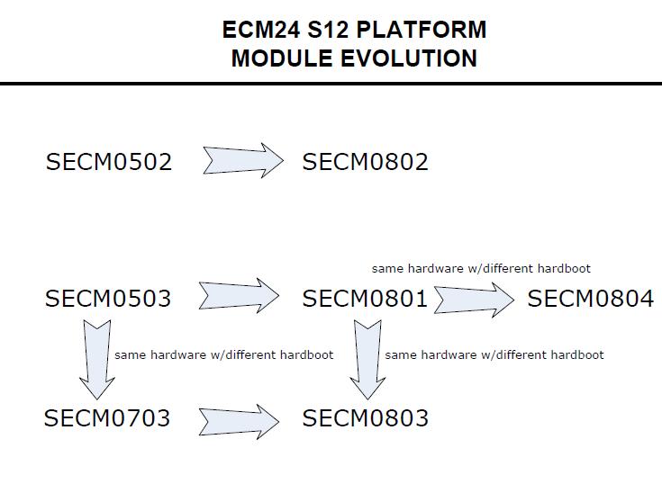
ECM/GCM-S12-24 Part Number Changes

- The SECM0502 is obsolete, replaced by SECM0802. These modules are functionally equivalent.
- The SECM0503 is obsolete, replaced by SECM0801. These modules are functionally equivalent.
- The SECM0804 is a "made" part, created from an SECM0801 with a different general-purpose hardboot loader.
- The SECM0703 is obsolete, replaced by SECM0803.
- The SECM0703 is a "made" part, created from an SECM0503 module with a customer-specific hardboot loader.
- Likewise, the SECM0803 is a "made" part, created from an SECM0801 module with that same customer-specific hardboot loader.
Notes on the ECM-S12-24 Part Number Migration
There are different software hardboots installed on the devices, but the physical hardware is identical.
| Device | Hardboot | City ID |
|---|---|---|
| SECM0801 (SECM0503) | "HB V1P2" | 129 = 0x81 |
| SECM0804 | "HB_4_3_RC1_PROD" | 11 = 0x0B |
The reason for the OEM part number changes, as from SECM0503 to SECM0801, is typically due to changing internal components (such as replacing a transistor that is end-of-life with a new, equivalent transistor) or similar issue. However, externally visible functionality is expected to be the same: i.e., the new OEM has the same ADC pull-up values, same input/output capabilities, etc.
Thus, the inputs/outputs are the same for SECM0503/SECM0801 and SECM0804.
We have Woodward part numbers for all products, but please work with the quotes team to make sure you get what you need. Of course, the tech support team can help, as required.
Difference Between ECM0801 and ECM0802
The 0801 is a variation of the 0802 with different pull up/pull down combinations for the analog ins and three ESTs have been replaced by more analog ins.
CAN Bus Limitations
The S12 modules do not support 1000K baud CAN bus speeds; they are hardware limited.
VR Signal Limits
The VR input maximum is 400v pp.
VR Circuit
The VR circuit is built upon the LM1815M integrated circuit. See the LM1815M's datasheet here.
Working with the S12 MotoHawk Application Document
Registered wiki users can download the "Working with the S12" application help. Understanding this document is imperative for using the S12-based MotoHawk modules. The document can be found here.
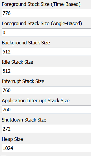
S12(X) Recommended Stack Size
The "Working with the S12" application document indicates a stack baseline when starting your application. Below is another recommended stack size if the stack baseline is low in certain areas.
NOTE: The following stack sizes are recommendations and should be adjusted according to the application requirements.

