Raptor-Dev-Input-&-Output: Difference between revisions
No edit summary |
No edit summary |
||
| (10 intermediate revisions by 2 users not shown) | |||
| Line 1: | Line 1: | ||
{{DISPLAYTITLE:Raptor-Dev Input&Output Library}} | {{DISPLAYTITLE:Raptor-Dev Input & Output Library}} | ||
{{Navigation}} [[Raptor-Platform | Raptor Platform]] > [[ | {{Navigation}} [[Raptor-Platform | Raptor Platform]] > [[Raptor-Dev]] > [[Raptor-Dev-Libraries | Raptor-Dev Library]] > '''Raptor-Dev Input & Output Library''' | ||
[[File:RaptorInputOutput.png|right|frame|Raptor™ Input and Output]] | [[File:RaptorInputOutput.png|right|frame|Raptor™ Input and Output]] | ||
<p>The blocks in this subsystem are access ECU hardware resources such as Analog Inputs and PWM Outputs.</p> | <p>The blocks in this subsystem are access ECU hardware resources such as Analog Inputs and PWM Outputs.</p> | ||
| Line 18: | Line 17: | ||
|- | |- | ||
! <h5>[[Raptor:Analog Output|Analog Output]]</h5> | ! <h5>[[Raptor:Analog Output|Analog Output]]</h5> | ||
| <p> | | <p>This block is used to control the state of an analog output.</p> | ||
| [[file:RaptorAnalogOutput.jpg|frameless|border|Analog Input block|center]] | | [[file:RaptorAnalogOutput.jpg|frameless|border|Analog Input block|center]] | ||
|- | |- | ||
Latest revision as of 14:09, 1 September 2016
New Eagle > Products Wiki > Raptor Platform > Raptor-Dev > Raptor-Dev Library > Raptor-Dev Input & Output Library
The blocks in this subsystem are access ECU hardware resources such as Analog Inputs and PWM Outputs.
Blocks
| Block | Description | Appearance |
|---|---|---|
Analog Input |
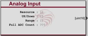
This block reads the value of an analog input. An analog input is typically a voltage input on an input pin to the module. This block outputs the raw analog to digital converter counts. The scaling factor to convert from counts to engineering units may be different for different inputs, sensors or modules. The Full ADC Count indicated on the block represents a guideline for the maximum expected ADC count based on the underlying hardware - values above this threshold may not correspond linearly to those within the range. |
 |
Analog Output |
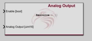
This block is used to control the state of an analog output. |
 |
Digital Input |
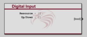
This block reads the value of a digital input. |
 |
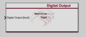
Digital Output |
This block sets the state of the selected digital output. |
 |
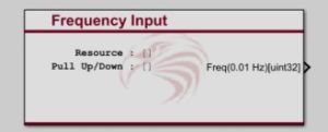
Frequency Input Block |
This block reads the value of a frequency input. Some modules also support duty cycle measurement through this input. |
 |
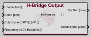
H-Bridge Output Block |
This block sets the state of the selected H-bridge output. An H-Bridge output is an output which uses 2 pins where either pin can be connected to V+ or V-. This type of output is typically used to drive DC motors which must move in both directions. |
 |
Internal Measurement |
This block reads the value of an an internal measurement. An internal measurement is a measured value which is internal to the control module. |
 |
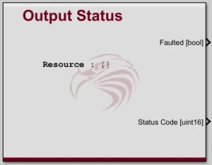
Output Status |
This block shows the status of the selected output. On modules which support output diagnostics this block can show if an output is shorted or shutdown do to over current. |
 |
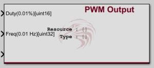
PWM Output |
This block sets the state of the selected PWM output. PWM (pulse width modulation) is typically used similar to an analog output. |
 |
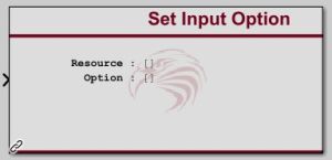
Set Input Option |
This block allows the range, filter and pull up/down of input blocks to be changed dynamically within a model. The option is changed when the block is executed. Until this block executes with a valid input for the first time the options of the input will be the value set in the input block. This block is target dependant. Place this block in a model with a target definition block and then enter the block's help again for more specific help. |
 |