Raptor:Modbus Master: Difference between revisions
Jump to navigation
Jump to search
(Created page with 'Return to the main Raptor page Return to Data Storage page right|frame|Raptor Adjustment == Description ==…') |
|||
| (14 intermediate revisions by the same user not shown) | |||
| Line 1: | Line 1: | ||
[[RaptorWiki|Return to the main Raptor page]] | [[RaptorWiki|Return to the main Raptor page]] | ||
[[Raptor | [[Raptor-Dev-Modbus-Library|Return to Modbus Library page]] | ||
[[File: | [[File:RaptorModbus.jpg|right|frame|Raptor Modbus Master]] | ||
== Description == | == Description == | ||
<p> | <p>This block acts as a [https://en.wikipedia.org/wiki/Modbus Modbus] master on a serial bus. The master requests data from slave device(s).</p> | ||
== Inputs == | == Inputs == | ||
| Line 14: | Line 14: | ||
! scope="col" style="width: 15%;"|Type | ! scope="col" style="width: 15%;"|Type | ||
! scope="col" style="width: 70%;"|Description | ! scope="col" style="width: 70%;"|Description | ||
|- | |||
! Node | |||
| uint16 | |||
| The address of the slave device to request from. | |||
|- | |||
! Register Address | |||
| uint16 | |||
| The register address to be read. | |||
|- | |||
! Read length | |||
| uint16 | |||
| The number of registers to be read. | |||
|- | |||
|} | |} | ||
== Outputs == | == Outputs == | ||
| Line 22: | Line 36: | ||
! scope="col" style="width: 15%;"|Type | ! scope="col" style="width: 15%;"|Type | ||
! scope="col" style="width: 70%;"|Description | ! scope="col" style="width: 70%;"|Description | ||
|- | |||
! RegisterRead() | |||
| trigger | |||
| The trigger port will fire when a valid response is received. | |||
|- | |||
! Node Address | |||
| uint16 | |||
| The address of the responding slave. | |||
|- | |||
! Data Address | |||
| uint16 | |||
| The register address for the start of the read. | |||
|- | |||
! data | |||
| uint16 | |||
| The data returned from the slave. | |||
|- | |||
|} | |} | ||
| Line 31: | Line 62: | ||
! scope="col" style="width: 70%;"|Description | ! scope="col" style="width: 70%;"|Description | ||
|- | |- | ||
! Name | ! Serial Bus Name | ||
| String | | String | ||
| | | The name of the serial bus that should be utilized. | ||
|- | |- | ||
! | ! Data Requests | ||
| String | | String | ||
| | | A list of data request that should be requested. See: modbus_requests_example.m for the format. | ||
|- | |- | ||
! | ! Use Inputs | ||
| | | checkbox | ||
| | | If checked the block will use input ports for the data requests. | ||
|- | |- | ||
|} | |} | ||
Latest revision as of 21:21, 28 November 2016
Return to the main Raptor page

Description
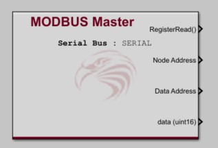
This block acts as a Modbus master on a serial bus. The master requests data from slave device(s).
Inputs
| Input | Type | Description |
|---|---|---|
| Node | uint16 | The address of the slave device to request from. |
| Register Address | uint16 | The register address to be read. |
| Read length | uint16 | The number of registers to be read. |
Outputs
| Output | Type | Description |
|---|---|---|
| RegisterRead() | trigger | The trigger port will fire when a valid response is received. |
| Node Address | uint16 | The address of the responding slave. |
| Data Address | uint16 | The register address for the start of the read. |
| data | uint16 | The data returned from the slave. |
Parameters
| Parameter | Type | Description |
|---|---|---|
| Serial Bus Name | String | The name of the serial bus that should be utilized. |
| Data Requests | String | A list of data request that should be requested. See: modbus_requests_example.m for the format. |
| Use Inputs | checkbox | If checked the block will use input ports for the data requests. |