Raptor:LIN Tx Message: Difference between revisions
Jump to navigation
Jump to search
(Created LIN Tx Message Page) |
No edit summary |
||
| Line 6: | Line 6: | ||
== Description == | == Description == | ||
<p>The LIN Tx Message block uses a frame definition from the LDF file associated with the LIN Bus definition block to transmit the frame on the specified bus. The transmission is scheduled according to the LIN frame schedule. | <p>The LIN Tx Message block uses a frame definition from the LDF file associated with the LIN Bus definition block to transmit the frame on the specified bus. The transmission is scheduled according to the LIN frame schedule. One Simulink Function can be triggered directly from this block, as if a LIN Trigger block had been used. The Simulink function should be placed somewhere along the calling block's path to model root. | ||
</p> | </p> | ||
| Line 39: | Line 39: | ||
| Checkbox | | Checkbox | ||
| Enable this to automatically name the wires on the input ports with the names of the signals | | Enable this to automatically name the wires on the input ports with the names of the signals | ||
|- | |||
! Use Simulink Function | |||
| checkbox | |||
| Whether to use a Simulink Function or a triggered subsystem. | |||
If a Simulink Function is used, it should be placed somewhere along the calling block's path to model root. | |||
|- | |||
! Simulink Function Name | |||
| String | |||
| Name of the Simulink Function to call when this block is triggered. | |||
|- | |||
! Create | |||
| button | |||
| Create a Simulink Function to use with the LIN Trigger block. | |||
Must first provide a valid function name. | |||
|- | |||
! Update | |||
| button | |||
| Update the listed Simulink Function's signature to 0 inputs & 0 outputs. | |||
The Simulink Function listed in the box must already exist. | |||
|} | |} | ||
Latest revision as of 19:32, 13 September 2023
Return to the main Raptor page

Description
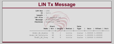
The LIN Tx Message block uses a frame definition from the LDF file associated with the LIN Bus definition block to transmit the frame on the specified bus. The transmission is scheduled according to the LIN frame schedule. One Simulink Function can be triggered directly from this block, as if a LIN Trigger block had been used. The Simulink function should be placed somewhere along the calling block's path to model root.
Inputs
| Input | Type | Description |
|---|---|---|
| Signal(s) | uint32 | Any signals from the .ldf for this message. |
Parameters
| Parameter | Type | Description |
|---|---|---|
| LIN Bus Name | Provides the logic LIN bus name on which to transmit. | |
| Frame | Identifies the frame that block will be configured to transmit, the frames are defined in the LDF file associated with the named LIN Bus. | |
| Label wires with channel names | Checkbox | Enable this to automatically name the wires on the input ports with the names of the signals |
| Use Simulink Function | checkbox | Whether to use a Simulink Function or a triggered subsystem.
If a Simulink Function is used, it should be placed somewhere along the calling block's path to model root. |
| Simulink Function Name | String | Name of the Simulink Function to call when this block is triggered. |
| Create | button | Create a Simulink Function to use with the LIN Trigger block.
Must first provide a valid function name. |
| Update | button | Update the listed Simulink Function's signature to 0 inputs & 0 outputs.
The Simulink Function listed in the box must already exist. |