GCM-563-48: Difference between revisions
Jump to navigation
Jump to search
| (4 intermediate revisions by one other user not shown) | |||
| Line 12: | Line 12: | ||
#The ANxM_DGxM pins may be configured as both analog and digital inputs at the same time; the intent is to allow the analog channel to be used for diagnostics of the digital channel. For these shared inputs, the DGxM time constant is 5.1 microseconds.<br><br> | #The ANxM_DGxM pins may be configured as both analog and digital inputs at the same time; the intent is to allow the analog channel to be used for diagnostics of the digital channel. For these shared inputs, the DGxM time constant is 5.1 microseconds.<br><br> | ||
#The 2.585k pull-down analog inputs have a 3kΩ pull-down in parallel with a 16.5k / 2.21k ohm voltage divider pull-down, with the Analog/Digital Converter such that:<br>ADC_counts = (1024 / 5.00) * (2.21 / (2.21 + 16.50)) * (V_pin) or<br>0 <= ADC_counts <= 1023 counts :: 0 <= V_pin <= 42.29 volts<br><br> | #The 2.585k pull-down analog inputs have a 3kΩ pull-down in parallel with a 16.5k / 2.21k ohm voltage divider pull-down, with the Analog/Digital Converter such that:<br>ADC_counts = (1024 / 5.00) * (2.21 / (2.21 + 16.50)) * (V_pin) or<br>0 <= ADC_counts <= 1023 counts :: 0 <= V_pin <= 42.29 volts<br><br> | ||
# | #The relationship between ECUP Analog/Digital Converter counts and KEYSW voltage for GCM-0563-048-08xx and HCM-0563-048-08xx:<br>ADC_counts_ECUP = (1024 / 5.00) * (2.21 / (2.21 + 16.50)) * (V_keysw - 0.7 volts) | ||
Please note that the default Main Power Relay block setting of | Please note that the default Main Power Relay block setting of 100ADC counts corresponds to approximately KEYSW = 4.8VDC. | ||
== GCM-563-048 Datasheet (36303) Errata== | == GCM-563-048 Datasheet (36303) Errata== | ||
| Line 37: | Line 37: | ||
==<div style="font-size:21px; width:75%; font-weight:bold; text-align:left; padding-top:7px; padding-bottom:7px; background:#800020; color:white;">Datasheets</div>== | ==<div style="font-size:21px; width:75%; font-weight:bold; text-align:left; padding-top:7px; padding-bottom:7px; background:#800020; color:white;">Datasheets</div>== | ||
'''[ | :'''[https://wiki.neweagle.net/ProductDocumentation/Controllers/GCM-563-48/GCM-0563-048_DataSheet.pdf Datasheet]''' | ||
==Other Modules== | ==Other Modules== | ||
| Line 43: | Line 43: | ||
== Webstore == | == Webstore == | ||
'''[https://store.neweagle.net/product-category/products/controllers/motohawk-controllers/gcm-general-control-modules/ 48- | '''[https://store.neweagle.net/product-category/products/controllers/motohawk-controllers/gcm-general-control-modules/ 48-Pin General Control Modules]''' | ||
'''[https://store.neweagle.net/product-category/products/controllers/ All Control Modules]''' | '''[https://store.neweagle.net/product-category/products/controllers/ All Control Modules]''' | ||
[[Category:Controllers]] | [[Category:Controllers]] | ||
Latest revision as of 18:00, 8 March 2023
Overview
These rugged controllers are capable of operating in harsh automotive, marine and off-highway applications. The onboard floating-point unit and high clock frequency allow software to be executed in short times. The CAN 2.0B datalink ensures interoperability with other vehicle systems. Each controller is available in flash or calibratable versions.
CCM and SIM Modules
The GCM-563-48 0801 and 0802 were also known as the CCM and SIM modules as part of the Fire48 MotoTron Controller Platform
- CCM48 = Command Control Module
- SIM48 = System Integration Module
GCM-563-048-0801 (CCM48) Notes
- The ANxM_DGxM pins may be configured as both analog and digital inputs at the same time; the intent is to allow the analog channel to be used for diagnostics of the digital channel. For these shared inputs, the DGxM time constant is 5.1 microseconds.
- The 2.585k pull-down analog inputs have a 3kΩ pull-down in parallel with a 16.5k / 2.21k ohm voltage divider pull-down, with the Analog/Digital Converter such that:
ADC_counts = (1024 / 5.00) * (2.21 / (2.21 + 16.50)) * (V_pin) or
0 <= ADC_counts <= 1023 counts :: 0 <= V_pin <= 42.29 volts - The relationship between ECUP Analog/Digital Converter counts and KEYSW voltage for GCM-0563-048-08xx and HCM-0563-048-08xx:
ADC_counts_ECUP = (1024 / 5.00) * (2.21 / (2.21 + 16.50)) * (V_keysw - 0.7 volts)
Please note that the default Main Power Relay block setting of 100ADC counts corresponds to approximately KEYSW = 4.8VDC.
GCM-563-048 Datasheet (36303) Errata
- Page 5 calls out DRVP as pin A23, which shows up as LSO7 in pages 4, 6 and 10
- Page 5 assigns Pin A15 to STOP whereas other pages assign B23 to STOP and A15 to AN13M/DG5M
- CAN1- appears to have quite a few redundant pins – A11, B11 and B21 (Pages 9 and 10)
Current Sense Capability for GCM-563-048
- The GCM-0563-048-0801 (CCM48) module has current sense on H1+ (high-side only).
- The GCM-0563-048-0802 (SIM48) module does NOT have current sense (either side).
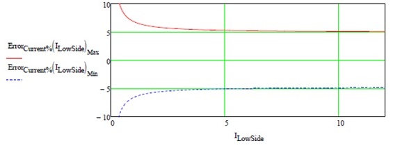
Here is the worst-case current sense accuracy % for LSD1-6 based on current level.
What is a Fire48 controller?
This is an engineering acronym for the GCM48 and HCM48 families.

