Engine and Transmission Controls: Difference between revisions
| Line 141: | Line 141: | ||
===Ground Support Equipment === | ===Ground Support Equipment === | ||
New Eagle has an LSI-certified Ford 4.9L application available today. | |||
==Compression Ignition Engines== | ==Compression Ignition Engines== | ||
Latest revision as of 19:32, 8 March 2023
Overview
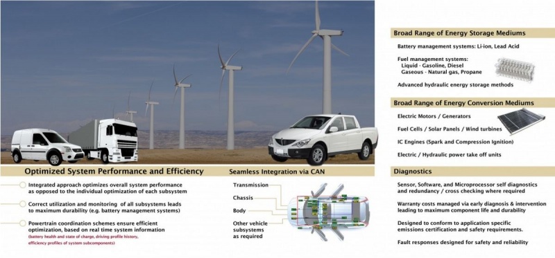
New Eagle has the following experience:
- Powertrain and vehicle modeling
- Engine calibration
- Model-based controls development methods
- Engine control algorithm development including port and direct injected fuel delivery, spark advance, bypass air, torque management, electronic throttle positioning, cylinder deactivation, cam phaser positioning and all associated diagnostics
- Interactive transmission controls for conventional automatic transmissions, CVT and DCTs
- Extensive experience working to OEM production requirements and utilizing industry best practice development methods and processes
- Experience working in partnership with Tier 1 suppliers, both domestically and internationally
- Supplier development, evaluation and selection
Integrated Powertrain Control
The New Eagle Engine Management Control System uses MotoHawk model-based development tools, processes and libraries. This is carried through from prototype through production. New Eagle has utilized the basic building blocks provided in this tool to create a set of high-level function libraries, which can be used to construct a complete powertrain management system to customer specifications.
Engine Control Library Blocks
The high-level building blocks in the New Eagle function library are shown below, along with a brief description of the functionality contained within:
Sensors
The hardware interface to all sensors, including resource assignments and basic ADC all the way to engineering unit conversions, is performed here. Functions in this block include:
- Analog inputs (pressures, temperatures, voltages, positions, flow rates, switch states, etc.)
- CAN inputs (same as above, but via CAN interface)
Actuators
The hardware interface to all actuators, including resource assignments and basic scaling all the way to ADC units, is performed here. Functions in this block include:
- Primary actuators (spark plugs, throttle body, fuel injectors, fuel pumps, "hardwired" lamps, etc.)
- Secondary actuators/accessories (alternator, fan, AC compressor, etc.)
Virtual Sensors
Within this block are the modeled sensors. The modeled sensors are state variables that have been created from available actual sensor information. This modeled sensor information is available to the higher-level control algorithms. Examples of functionality contained within this block include:
- Modeled air charge
- Engine running timers
- Engine state determination (cranking, running, stall, etc.)
- Steady-state determination
- Modeled temperatures
- Lambda (wide range O2 and switch type sensors)
Diagnostics Sensors Overrides
This block provides a means of replacing the sensor value with a default value when the diagnostic algorithms deem it appropriate, based on the severity of the fault that has been identified.
Base Algorithm Controller
This block contains the core high-level functionality of the control system. It contains most of the functions required for basic engine operation. Some examples of functions contained within this block include:
- Pedal interpretation as a torque requestor
- Cruise control
- PTO control
- Torque limiting functions (over-speed, over-rev, interface to transmission limiting requests and ABS limiting requests)
- Torque arbitration
- Open-loop fuel control
- Closed-loop fuel control
- Upstream control (wide-band and switch type control available)
- Downstream control (switch type control only)
- Intake airflow characterizations and dynamics
- Idle control (utilizing slow and fast path torque actuators)
- Deceleration fuel cutoff and safety fuel cutoff (DFCO/FC)
- Ignition angle and energy characterization as a function of speed, load, temperatures, pressures, knock, etc.
- Engine torque characterization – forward path (friction and pumping losses, indicated engine torque to air charge characterization, modifiers for ignition retard from MBT as scheduled from base spark control, temperature and pressure modifiers, equivalence ratio modifier, ignition angle offset request based on fast path torque, torque reserve request, and slow path/fast path coordination, DFCO/FC)
- Engine torque characterization – reverse path (friction and pumping losses, air charge to torque characterization, modifiers for ignition retard from MBT, equivalence ratio modifier, temperature and pressure modifiers, DFCO/FC).
- Accessory control (fan, AC, alternator, etc.)
Component Control
This block contains control algorithms linked to specific actuator hardware. Functions contained within this block include:
- Throttle position controller
- Throttle learning algorithm
- Ice breaking algorithm
- Certain customer specific actuators
- HEGO heater control
Diagnostics Actuators Overrides
This block provides a means of replacing the commanded value with a default value when the diagnostic algorithms deem it appropriate, based on the severity of the fault that has been identified.
Characterization
This block provides conversions from engineering units to the hardware-level units.
- Fuel mass to injector pulse width conversion (with appropriate temperature, pressure, voltage corrections)
- Ignition angle and spark energy to ignition coil start and stop angles
Drive By Wire Redundant Calculations and Diagnostics
This block contains all of the functionality required to validate all inputs and calculations resulting in the positioning of the throttle blade. These functions include:
- Sensor rationalities with redundant and modeled sensors
- Torque path calculations with redundant sensor set
- Main checking micro with secondary checking micro (cross-checking by each micro to monitor the state of health of the other micro)
- 3 Level torque safety structure
OBDII Diagnostics
OBD blockset integration aiming to be compliant with OBDII 1968.2
- Sensors: input high, input low, rate high, rate low
- Actuators: open/shorted
- CAN inputs: rate
OBDII Major Monitors and Rationalities
This block contains the major monitors and rationalities. Examples of functions contained within this block include:
- Fuel system monitor
- Catalyst monitor
- Simple misfire
- Catalyst temperature model (utilized by the catalyst monitor and certain base algorithm functions).
- Engine coolant temperature monitor
Communications and Reporting
This block includes the interfaces required for J1939 communications, freeze frames, etc., as required for diagnostics tools and customer specific tools such as "in-plant" and "end of line". Communications interfaces to other systems are also provided, such as:
- Cluster
- Body controller
- Transmission controller
- Chassis controller
- CCP support
Standard Engine Controller
Standard Engine Controller in Development
Spark Ignited Engines
General Offering
- Automotive quality and prices for components including sensors, throttles and engine controllers
- Enhanced user interface for engine control and system installation and setup
- Auto Start/Stop features for scheduled duty cycle or remote engine and load control
- Fuel efficiency advantages by utilizing automotive-style torque control algorithms
- OBD diagnostics to protect engine and other system components
- Adaptive to multiple fuel usage
- Adaptable controls for mobile and stationary applications
- Experience with vapor-lock handling and purge routines
Ground Support Equipment
New Eagle has an LSI-certified Ford 4.9L application available today.
Compression Ignition Engines
General Offering
This section is in development.
Fire Protection Systems
Electronic Engines
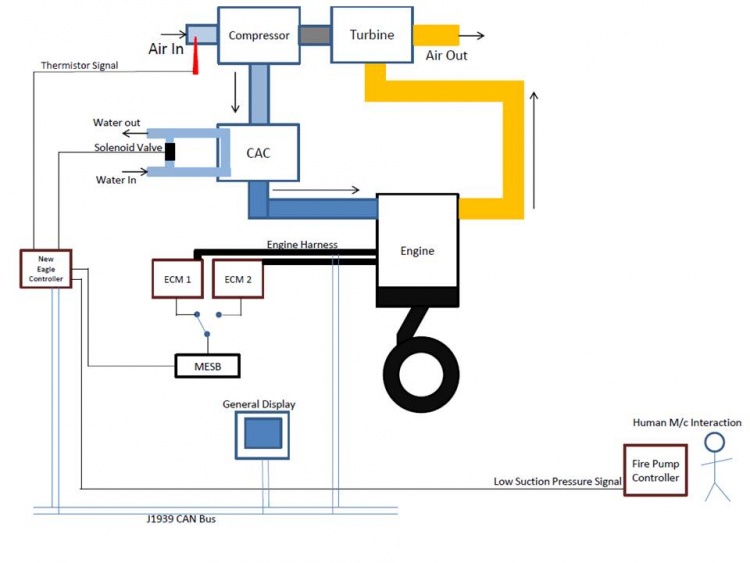
An electronic engine fire control system integrates an engine control unit with additional I/O and logic to perform fire control functions. Communication with the engine control unit is done over a data bus such as the J1939 CAN bus interface.
System Inputs and Outputs
Typical system I/O for the electronic engine consists of:
- SCB Replacement
- Valve output
- Current feedback of the valve output
- General fault alarm output
- Thermistor in pump - ambient temperature
- Bypass valve output - optional
- Thermistor input - raw water - optional
- Suction Pressure Alarm
- Alarm output
- ECM Supervisory Switch
- ECM switch driver
- Alarm - primary/alternate ECM failure, engine running alarm
Mechanical Engines
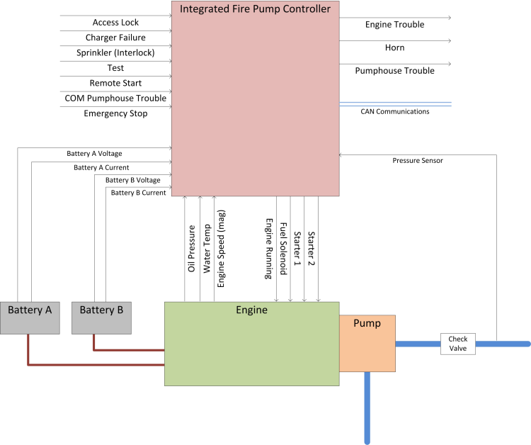
A Mechanical Engine Fire Control System does not interface with a data bus and therefore requires control and signal inputs and outputs.
System Inputs and Outputs
Typical system I/O for the mechanical engine consists of:
- Remote start/stop
- COM pumphouse trouble
- Emergency stop
- Sprinkler (interlock)
- Charger failure
- Access lock
- Oil pressure sensor
- Water temperature sensor
- Pressure sensor
- Mag pickup
- Engine running
- Fuel solenoid
- Horn
- Starters 1 and 2
- Engine/Pumphouse trouble
Heavy Fueled Engines
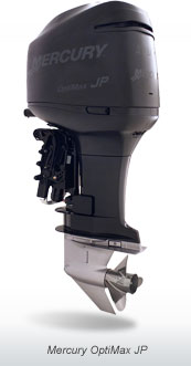
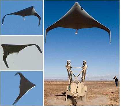
Members of New Eagle's engineering team have been working on applying the electronic fuel injection (EFI) system built in MotoHawk on UAV engines. The benefit of the MotoHawk system to the UAV is that the electronics and software have millions of hours of operation including use on the JP Marine heavy fuel engine.
One unique feature of the New Eagle EFI system is that it burns heavy fuels, JP5, JP8 and Jet A fuel. Derivatives of the EFI system have run on the UEL Rotary engine and the xRDI Heavy Fuel engine.
The New Eagle EFI system has been developed and tested on various airframes:
- AAI Shadow
- Raytheon KillerBee
- AeroMech SandDragon
xRDI
xRDI of Beaufort, South Carolina has a number of applications using the New Eagle EFI system.
Current xRDI projects include:
- Engine replacement for Unmanned Aerial Vehicle (UAV), 35 hp
- Auxiliary Power Unit (APU) for business jets, 17 hp with starter generator
- Flight demonstration and engine evaluation program with major airframe supplier, 17 hp
- Flight demonstration and engine evaluation program, 35 hp
- STUAS - Tier 2, Navy and Marine joint program for ship-based UAV, 15 hp
- Unmanned Ground Vehicle, 6 hp with starter generator
- SBIR Darpa Program for a 10 hp small engine designed for high efficiency, high power density and quiet operations
- Development program for a 3-cylinder and 4-cylinder heavy fuel engine for UAV application
OBD Diagnostics
- Reduces service time from troubleshooting
- Protects engine from harmful conditions such as low oil
- Reduces engine and system component warranty costs through system protections
- Prognostics available for scheduled service intervals
- Remote communications for system status available
- Ability to meet and exceed emissions requirements based on application
Transmission Controls
New Eagle’s team of engineers has had vast experience in the development, integration and deployment of controls, including but not limited to the following:
- Torque-based control
- Chassis powertrain controls
- Active braking
- ESP stability
- Interaction based on torque messaging
- Powertrain coordination schemes
- Optimization
- More for diesel and gasoline engines both
Using this experience, New Eagle, as controls integrators, seeks to accomplish even more challenging projects in the future. We believe we have the correct solution to meet the needs of all our customers, whether it is a specific demand or a simpler challenge. Not only that, but our experience over the years has also given us the capabilities to ensure success with our reliability, robustness, performance and support for our projects.
