Bench Tools: Difference between revisions
| (109 intermediate revisions by 12 users not shown) | |||
| Line 1: | Line 1: | ||
'''[[MotoHawk Control Solutions#Bench_Tools|MotoHawk Control Solutions/Bench Tools]]''' | <!--'''[[MotoHawk Control Solutions#Bench_Tools|MotoHawk Control Solutions/Bench Tools]]'''--> | ||
==Breakout | ==Breakout Box == | ||
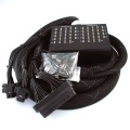
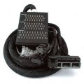
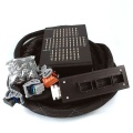
Performing ECM signal measurement and failure testing without modifying the harness can be difficult and time consuming. ECM breakout boxes are rugged harness inserts designed to make this painful job easy. Breakout boxes were designed by application developers to assist troubleshooting and failure mode testing activities and are a highly recommended part of every developer's toolkit. The family of breakout boxes covers | Performing ECM signal measurement and failure testing without modifying the harness can be difficult and time consuming. ECM breakout boxes are rugged harness inserts designed to make this painful job easy. Breakout boxes were designed by application developers to assist troubleshooting and failure mode testing activities and are a highly recommended part of every developer's toolkit. The family of breakout boxes covers both Raptor and MotoHawk modules. The breakout box plugs into the existing harness connectors and ECM, but also provides an extension with measurement points and circuit breaking bars. Each pin to the ECM can be probed, open circuited, or connected to any other signal. Each breakout box assembly comes with an expander toolkit of patch cables, shorting bars and banana jacks. | ||
==== | ====Products==== | ||
<gallery perrow=4> | |||
File:Breakout box 48 pin.jpg|48-pin breakout box | |||
File:ASM-BBOX-70-1002.jpg|70- and 80-pin breakout box | |||
File:Breakout box 112 pin.jpg|112-pin breakout box | |||
File:ASM-BBOX-196.jpg|196-pin breakout box | |||
</gallery> | |||
== | ===== Webstore ===== | ||
'''[https://store.neweagle.net/shop/products/connectors-tools/break-out-boxes-connectors-tools/raptor-48-pin-breakout-box-with-test-lead-kit-for-gcm48/ ASM-BBOX-GCM48]''' <br> | |||
'''[https://store.neweagle.net/shop/products/connectors-tools/break-out-boxes-connectors-tools/raptor-70-pin-breakout-box-with-test-lead-kit-for-gcm70/ ASM-BBOX-GCM70]''' <br> | |||
'''[https://store.neweagle.net/shop/products/connectors-tools/break-out-boxes-connectors-tools/raptor-80-pin-breakout-box-with-test-lead-kit-for-gcm80/ ASM-BBOX-GCM80]''' <br> | |||
'''[https://store.neweagle.net/shop/products/connectors-tools/break-out-boxes-connectors-tools/raptor-80-pin-breakout-box-with-test-lead-kit-for-rcm80/ ASM-BBOX-RCM80]''' <br> | |||
'''[https://store.neweagle.net/shop/products/connectors-tools/break-out-boxes-connectors-tools/raptor-112-pin-breakout-box-with-test-lead-kit-for-rcm112/ ASM-BBOX-RCM112]''' <br> | |||
'''[https://store.neweagle.net/shop/products/connectors-tools/break-out-boxes-connectors-tools/196-pin-breakout-box-with-test-lead-kit/ ASM-BBOX-GCM196]''' | |||
==== | ====[https://store.neweagle.net/product-category/products/connectors-tools/break-out-boxes-connectors-tools/ Breakout Box Assemblies]==== | ||
== | ====Drawing==== | ||
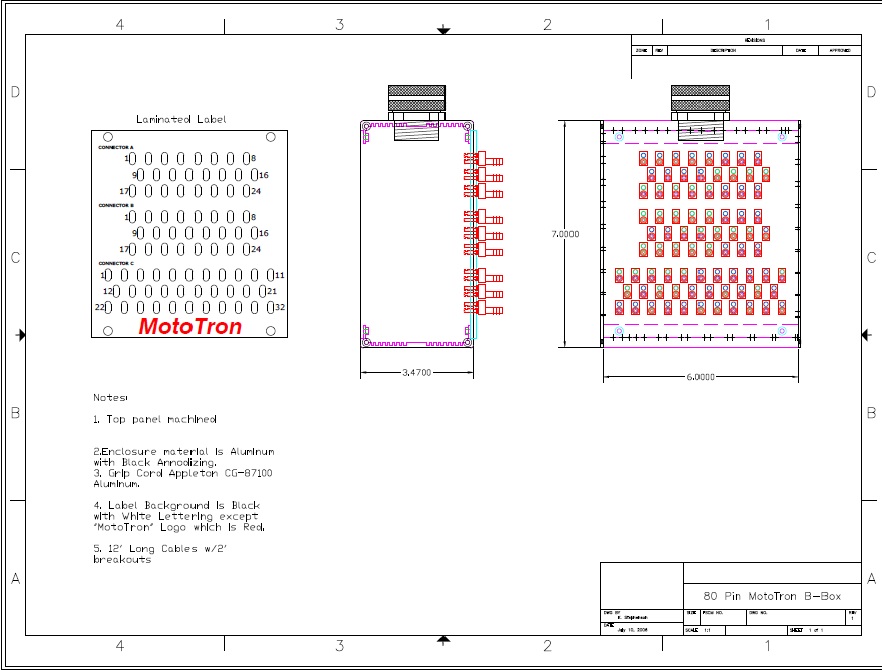
New Eagle 48-pin breakout box | |||
=== | [[File:40 pin New Eagle Breakout box.jpg]] | ||
New Eagle 80-pin breakout box | |||
[[File:80 pin Breakout box.jpg]] | |||
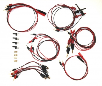
===Breakout Box Assembly Expansion Kit=== | |||
New Eagle offers an expansion kit for any breakout box. | |||
The kit includes the following 28 components: | |||
Mini Alligator - BNC 4 total | |||
Mini Alligator - Mini Banana 2 Pair (4 total) | |||
Mini Banana - Mini Banana 2 Pair (4 total) | |||
Mini Grabber - Mini Banana 2 Pair (4 total) | |||
Banana - Mini Banana 2 Pair (4 total) <br/> | |||
Breakout Box Connectors 4 total | |||
Shorting Bars 4 total | |||
[[File:Asm-bbox-kit.jpg|350px]] | |||
==Desktop I/O Simulator (Obsolete - Not Available) == | |||
The MotoHawk Desktop I/O Simulator is a handy tool for bench development and testing. It allows you to adjust analog input levels with potentiometers, monitor output, test application scenarios, etc., without needing actual sensor connections. If you are interested, please contact [mailto:sales@neweagle.net sales@neweagle.net]. The part number is ASM-CNDV-002. | |||
'''ASM-CNDV-002 - ''' | |||
'''Please contact sales for more information: [mailto:sales@neweagle.net sales@neweagle.net]''' | |||
[[image:desksim1.png|right]] | [[image:desksim1.png|right]] | ||
The Desktop I/O Simulator is designed to assist in developing control programming for a MotoHawk ECM; this practical device enables you to more easily simulate and adjust analog input levels (via onboard potentiometers), monitor output, test application scenarios, etc., without requiring the actual sensor connections. | The Desktop I/O Simulator is designed to assist in developing control programming for a MotoHawk ECM; this practical device enables you to more easily simulate and adjust analog input levels (via onboard potentiometers), monitor output, test application scenarios, etc., without requiring the actual sensor connections. | ||
The Simulator has I/O, CAN connections, power and ground channels, | The Simulator has I/O, CAN connections, power and ground channels, key-switch, and other features as applicable, which map to the respective resources of the ECM in use. | ||
Connect the MotoHawk ECM to the Simulator | Connect the MotoHawk ECM to the Simulator using the appropriate available harness. Connect a computer with programming and calibration tools to the ECM via CAN or RS485 connection to the mounted CAN junction box or floating connectors. Then use the Simulator to adjust input levels, drive output loads, monitor I/O signals and verify parameters, and as a result better understand and adjust the control programming needed, without using actual application hardware. | ||
===Specifications=== | ===Specifications=== | ||
::*Aluminum frame, angle-mounted for ease of use, with scratch-free rubber feet | ::*Aluminum frame, angle-mounted for ease of use, with scratch-free rubber feet | ||
::*Over 200 banana jacks in total for I/O - connect inputs or meters/oscilloscope to outputs | ::*Over 200 banana jacks in total for I/O - connect inputs or meters/oscilloscope to outputs | ||
::*30 Channels of Analog Input (switchable - On / Off) with dedicated potentiometer sliders | ::*30 Channels of Analog Input (switchable - On/Off) with dedicated potentiometer sliders | ||
::*45 Channels of Low or High Side Output (switchable - On / Off) | ::*45 Channels of Low- or High-Side Output (switchable - On/Off) | ||
::*3 CAN Channels (switchable - On / Off) | ::*3 CAN Channels (switchable - On/Off) | ||
::*1 RS485 Channel (switchable - On / Off) | ::*1 RS485 Channel (switchable - On/Off) | ||
::*8 Digital Inputs (switchable - On / Off or pulled High / Low) | ::*8 Digital Inputs (switchable - On/Off or pulled High/Low) | ||
::*10 Power and Ground Channels (switchable - On / Off) , including ECM Input Voltage+/-, XDRP, XDRG, MPRD, DRVP, | ::*10 Power and Ground Channels (switchable - On/Off), including ECM Input Voltage+/-, XDRP, XDRG, MPRD, DRVP, DVRG and Key-Switch | ||
::*4 Knock sensor inputs | ::*4 Knock sensor inputs | ||
::*4 CAM/Crank inputs | ::*4 CAM/Crank inputs | ||
| Line 43: | Line 75: | ||
===Setup=== | ===Setup=== | ||
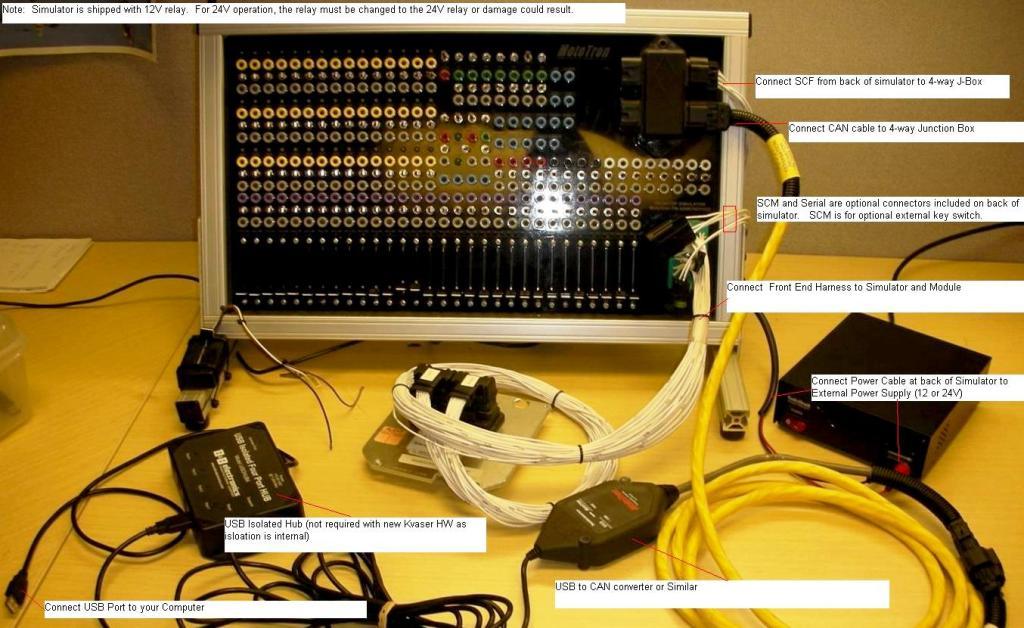
'''Make the following connections:''' | '''Make the following connections:''' | ||
::*SCF: Plug connector labeled SCF on the back of the simulator into the 4-way junction box on the front of the simulator | ::*SCF: Plug the connector labeled SCF on the back of the simulator into the 4-way junction box on the front of the simulator. | ||
::*Power Cable:Plug the power supply cables on the back of the simulator into your power supply. | ::*Power Cable: Plug the power supply cables on the back of the simulator into your power supply. | ||
::*CAN: Connect your CAN or communications cable (sold separately) into the Simulator 4-way | ::*CAN: Connect your CAN or communications cable (sold separately) into the Simulator 4-way junction box. | ||
'''Optional Connections:''' | '''Optional Connections:''' | ||
::*SCM: Optional connector for external key switch | ::*SCM: Optional connector for external key-switch | ||
::*Serial: Optional connector for external serial communications | ::*Serial: Optional connector for external serial communications | ||
[[image:desksim2. | [[image:desksim2.jpg]] | ||
===Power and Ground Channels=== | ===Power and Ground Channels=== | ||
'''Warning: Simulator is configured for 12V systems. For 24V systems, the relay connected on the backside must be changed to the 24V relay or failure may occur.''' | '''Warning: Simulator is configured for 12V systems. For 24V systems, the relay connected on the backside must be changed to the 24V relay or failure may occur.''' | ||
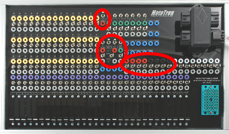
The Power and Ground Channels are located in the center of the Simulator, and include BATT, XDRP A/B, XDRG, MPRD, DRVP, | The Power and Ground Channels are located in the center of the Simulator, and include BATT, XDRP A/B, XDRG, MPRD, DRVP, DVRG, EST RTN and Key-Switch. These are connected to the ECM via the harness, though the jacks allow optional external connections. | ||
[[image:desksim3.png]] | [[image:desksim3.png]] | ||
Note: Connection to a | Note: Connection to a 12VDC (nominal) power supply is required. The Desktop I/O Simulator has a positive and a negative connector for use with a power supply. Do not use a supply higher than 36VDC, as the LED circuits are not able to withstand this. | ||
[[image:desksim4.png|left]] | [[image:desksim4.png|left]] | ||
| Line 66: | Line 98: | ||
::*'''KEY SWITCH''' | ::*'''KEY SWITCH:''' The KEY SWITCH interface includes a top, vertical-direction ON/OFF switch, which connects directly to the key-switch (ECUP) input to the ECM, to turn the ECM key-switch on/off. The other, side-to-side switch enables/disables the ON/OFF function of the top switch. The red jack allows connection of an external key-switch input. '''Note:''' Some ECMs use the key-switch input, others do not. Refer to the datasheet for your ECM. | ||
::*'''MANUAL/DVRP''' | ::*'''MANUAL/DVRP:''' You can turn the DVRP to the ECM on/off via the MANUAL/DVRP ON/OFF switch, if the DVRP switch (below) is set to MANUAL. The other, side-to-side switch enables/disables the ON/OFF function of the top switch. | ||
::*'''DVRP''' | ::*'''DVRP:''' You can turn the MANUAL DVRP on/off via the DVRP ON/OFF switch. When the switch is OFF, the DRVP power is automatically supplied. When ON, use of the MANUAL DVRP ON/OFF switch controls the DVRP power. | ||
::*'''LEDs''' | ::*'''LEDs:''' The MPRD indicator LED is ON when MPRD power is ON (as a result of turning on the ECM). The DVRP indicator LED in ON to indicate the DVRP power to the ECM is ON. | ||
::*'''STOP (DG8)''' | ::*'''STOP (DG8):''' The STOP interface includes a top, vertical-direction LOW/PULL-UP, which connects directly to the E-STOP input to the ECM (the DG8 input acts as a STOP input on the 128-pin ECM). The other, side-to-side switch enables/disables the ON/OFF function of the top switch. The red jack allows connection of an external STOP input. | ||
[[image:desksim5.png|left]] | [[image:desksim5.png|left]] | ||
| Line 79: | Line 111: | ||
::*'''XDRP A/B:''' The two XDRP jacks, A and B, each include a side-to-side ON/OFF switch, which turns the respective transducer power on/off. | |||
::*'''BATT:''' You can turn the battery power to the ECM on/off via the BATT ON/OFF switch. | |||
::*'''MPRD:''' You can turn the power to the main power relay driver on/off via the MPRD ON/OFF switch. | |||
::*'''LEDs:''' (see drawing above) The MPRD indicator LED is ON when MPRD power is ON (as a result of turning on the ECM). The DVRP indicator LED in ON to indicate the DVRP power to the ECM is ON. | |||
[[image:desksim6.png|left]] | |||
::*'''EST RTN:''' The EST RTN input provides connection to the EST return resource on the connected ECM. You can connect or disconnect the EST return to the ECM via the EST RTN ON/OFF switch. | |||
::*'''XDRG:''' You can connect or disconnect the transducer ground to the ECM via the XDRG ON/OFF switch. | |||
::*'''GROUND:''' You can connect or disconnect the power ground to the ECM via the GROUND ON/OFF switch. | |||
::*'''DVRG:''' You can connect or disconnect the driver ground to the ECM via the DVRG ON/OFF switch. | |||
===Communications=== | |||
The Simulator supports connecting up to three CAN channels and an RS-485 channel. The jacks are located at the right side of the Simulator just below the junction box and above the harness connector. Each connection includes an OFF/ON switch to disable/enable the channel connection. | |||
[[image:desksim7.png]] | |||
===Output Sections=== | |||
These outputs connect to your ECM output pins by designation and in order of resource number. Refer to the datasheet for your particular ECM for resources available. Depending on the resources of the particular ECM in use, some of the Simulator output jacks may not be in use. | |||
[[image:desksim8.png|left]] | |||
::*'''LEDs:''' The LEDs above the outputs show status; LEDs turn on green if a low-side output is active and set up as “low-side,” for example, and show red if the output is active as “high-side.” | |||
::*'''ON/OFF:''' You can turn the output on/off via the switch. When off, the yellow (top) jack is inactive; the monitor (gray) jack is usable with the switch in either the ON or OFF position. | |||
::*'''Output jacks:''' The top jack (yellow) of each output directly connects to the respective ECM output resource. Output characteristics of the respective ECM resource are thus conveyed. | |||
The lower (gray) jacks are the respective voltage-level monitors only. | |||
| Line 103: | Line 151: | ||
====Low Side Outputs==== | ====Low-Side Outputs==== | ||
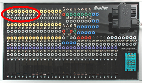
Labeled LSO1-LSO8, eight | Labeled LSO1-LSO8, eight low-side outputs are located in the upper left corner of the Simulator. | ||
[[image:desksim9.png]] | [[image:desksim9.png]] | ||
====INJ Outputs==== | ====INJ Outputs==== | ||
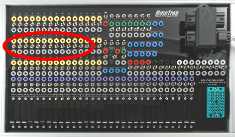
Labeled INJ1-INJ12, twelve fuel injector | Labeled INJ1-INJ12, twelve fuel injector outputs are located at the left side of the Simulator. | ||
[[image:desksim10.png]] | [[image:desksim10.png]] | ||
====EST Outputs==== | ====EST Outputs==== | ||
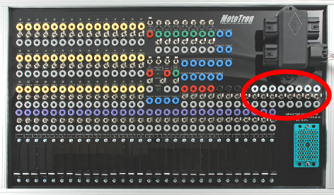
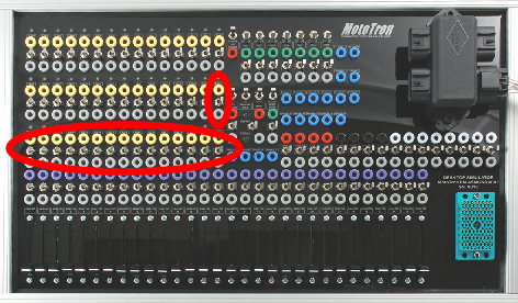
Labeled EST1-EST16, the 16 electronic spark timing | Labeled EST1-EST16, the 16 electronic spark timing outputs are located at the left side of the Simulator. | ||
'''Note''' | '''Note:''' In order to see EST firing indications, turn the respective EST LED ON/OFF switch to OFF. | ||
[[image:desksim11.png]] | [[image:desksim11.png]] | ||
====H-Bridge Outputs==== | ====H-Bridge Outputs==== | ||
Labeled H1+, H1-, H2+, H2-, | Labeled H1+, H1-, H2+, H2-, H3+ and H3-, the six H-bridge connections are located at the top center of the Simulator. | ||
| Line 146: | Line 181: | ||
===Analog/Digital Input Sections=== | ===Analog/Digital Input Sections=== | ||
====Analog Inputs==== | ====Analog Inputs==== | ||
Labeled Analog 1 | Labeled Analog 1 through Analog 30, the analog inputs (switchable - On/Off) are located along the bottom of the simulator, together with dedicated potentiometer sliders, 0-5V. | ||
Note: To connect your own sensor, use the gray jack | '''Note:''' To connect your own sensor, use the gray jack and switch the corresponding ON/OFF switch to OFF. | ||
[[image:desksim13.png|left]] | [[image:desksim13.png|left]] | ||
[[image:desksim14.png]] | [[image:desksim14.png]] | ||
====Digital Inputs==== | ====Digital Inputs==== | ||
The Simulator supports up to seven digital inputs, labeled DG1-DG7. The jacks are located at top center of the Simulator. | |||
[[image:desksim15.png]] | |||
The digital inputs each have a switch for setting input to low or pull-up, along with ON/OFF switches. | |||
[[image:desksim16.png|left]] | |||
::*'''LOW/PULL-UP:''' Switch input as needed for either pull-down or pull-up connection. | |||
::*'''Input jacks:''' The top jack (green) of each output directly connects to the respective ECM input resource. | |||
::*'''ON/OFF:''' You can turn the input on or off via the switch. When off, the green (top) jack is inactive; the monitor (gray) jack is usable with the switch in either the ON or OFF position. | |||
====Knock Sensor Inputs==== | ====Knock Sensor Inputs==== | ||
==== | Labeled Knock0 -/+ and Knock1 -/+, the four knock sensor connector jacks are located in the center of the Simulator. There are no associated switches or monitors; user must supply the knock input signal to the Simulator. | ||
[[image:desksim17.png]] | |||
====CAM/Crank Inputs==== | |||
The four CAM and Crank inputs are located at the top of the Simulator, labeled CAM and DG CAM, and Crank+/-. There are no associated switches or monitors; user must supply the respective sensor input signal to the Simulator. | |||
[[image:desksim18.png]] | |||
===Miscellaneous Non-Assigned Jacks=== | |||
There are 11 non-assigned jacks, reserved for future assignment. | |||
[[image:desksim19.png]] | |||
===Simulator Harnesses=== | ===Simulator Harnesses=== | ||
Get the appropriate harness for the ECM in use. Note, these are not available in the webstore but only by contacting [mailto:sales@neweagle.net sales@neweagle.net]. | |||
{| border=1 | |||
| '''Harness #''' | |||
|'''ECM Family''' | |||
|- | |||
| HARNINTR023A | |||
| To 24-Pin - GCM0565024/ECM0S12024 (ISDL/SECM) | |||
|- | |||
| HARNINTR023B | |||
| To 24-Pin - GCM0S12024 (MCHI/MSIM/SMUX) | |||
|- | |||
| HARNINTR024A | |||
| To 48-Pin - ECM0555048 | |||
|- | |||
| HARNINTR024B | |||
| To 48-Pin - ECM0563048 | |||
|- | |||
| HARNINTR024C | |||
| To 48-Pin - GCM0563048/HCM0563048 (FIRE 48) | |||
|- | |||
| HARNINTR025A | |||
| To 80-Pin - ECM0555080 | |||
|- | |||
| HARNINTR026A | |||
| To 112-Pin - ECM555x112 | |||
|- | |||
| HARNINTR027A | |||
| To 128-Pin - ECM0565128 | |||
|} | |||
Connect the required harness to the harness connector on the Simulator. | |||
[[image:desksim20.png]] | |||
Latest revision as of 19:13, 20 February 2023
Breakout Box
Performing ECM signal measurement and failure testing without modifying the harness can be difficult and time consuming. ECM breakout boxes are rugged harness inserts designed to make this painful job easy. Breakout boxes were designed by application developers to assist troubleshooting and failure mode testing activities and are a highly recommended part of every developer's toolkit. The family of breakout boxes covers both Raptor and MotoHawk modules. The breakout box plugs into the existing harness connectors and ECM, but also provides an extension with measurement points and circuit breaking bars. Each pin to the ECM can be probed, open circuited, or connected to any other signal. Each breakout box assembly comes with an expander toolkit of patch cables, shorting bars and banana jacks.
Products
-
48-pin breakout box
-
70- and 80-pin breakout box
-
112-pin breakout box
-
196-pin breakout box
Webstore
ASM-BBOX-GCM48
ASM-BBOX-GCM70
ASM-BBOX-GCM80
ASM-BBOX-RCM80
ASM-BBOX-RCM112
ASM-BBOX-GCM196
Breakout Box Assemblies
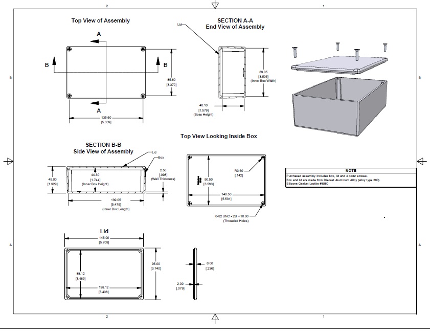
Drawing
New Eagle 48-pin breakout box
New Eagle 80-pin breakout box
Breakout Box Assembly Expansion Kit
New Eagle offers an expansion kit for any breakout box. The kit includes the following 28 components:
Mini Alligator - BNC             4 total
Mini Alligator - Mini Banana     2 Pair (4 total)
Mini Banana    - Mini Banana     2 Pair (4 total)
Mini Grabber   - Mini Banana     2 Pair (4 total)
Banana         - Mini Banana     2 Pair (4 total)

Breakout Box Connectors          4 total
Shorting Bars                    4 total
Desktop I/O Simulator (Obsolete - Not Available)
The MotoHawk Desktop I/O Simulator is a handy tool for bench development and testing. It allows you to adjust analog input levels with potentiometers, monitor output, test application scenarios, etc., without needing actual sensor connections. If you are interested, please contact sales@neweagle.net. The part number is ASM-CNDV-002.
ASM-CNDV-002 - Please contact sales for more information: sales@neweagle.net
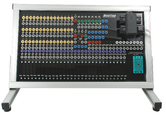
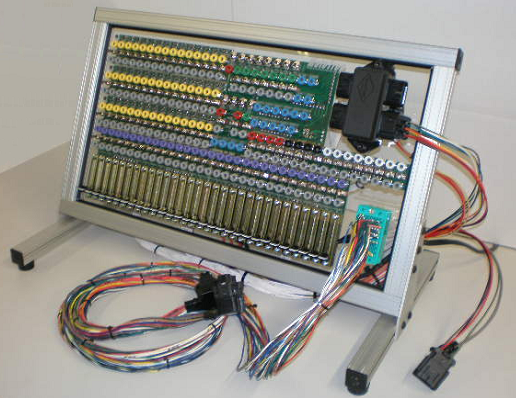
The Desktop I/O Simulator is designed to assist in developing control programming for a MotoHawk ECM; this practical device enables you to more easily simulate and adjust analog input levels (via onboard potentiometers), monitor output, test application scenarios, etc., without requiring the actual sensor connections. The Simulator has I/O, CAN connections, power and ground channels, key-switch, and other features as applicable, which map to the respective resources of the ECM in use. Connect the MotoHawk ECM to the Simulator using the appropriate available harness. Connect a computer with programming and calibration tools to the ECM via CAN or RS485 connection to the mounted CAN junction box or floating connectors. Then use the Simulator to adjust input levels, drive output loads, monitor I/O signals and verify parameters, and as a result better understand and adjust the control programming needed, without using actual application hardware.
Specifications
- Aluminum frame, angle-mounted for ease of use, with scratch-free rubber feet
- Over 200 banana jacks in total for I/O - connect inputs or meters/oscilloscope to outputs
- 30 Channels of Analog Input (switchable - On/Off) with dedicated potentiometer sliders
- 45 Channels of Low- or High-Side Output (switchable - On/Off)
- 3 CAN Channels (switchable - On/Off)
- 1 RS485 Channel (switchable - On/Off)
- 8 Digital Inputs (switchable - On/Off or pulled High/Low)
- 10 Power and Ground Channels (switchable - On/Off), including ECM Input Voltage+/-, XDRP, XDRG, MPRD, DRVP, DVRG and Key-Switch
- 4 Knock sensor inputs
- 4 CAM/Crank inputs
- 11 Non-assigned banana jacks
Depending on the ECM resources available, some of the jacks may not be mapped or connected to any resource from the ECM. Refer to the datasheet for your particular ECM to determine the resources available. It is best to check and verify the presence of the intended Simulator/ECM resource before attempting to apply in a test scenario.
Setup
Make the following connections:
- SCF: Plug the connector labeled SCF on the back of the simulator into the 4-way junction box on the front of the simulator.
- Power Cable: Plug the power supply cables on the back of the simulator into your power supply.
- CAN: Connect your CAN or communications cable (sold separately) into the Simulator 4-way junction box.
Optional Connections:
- SCM: Optional connector for external key-switch
- Serial: Optional connector for external serial communications
Power and Ground Channels
Warning: Simulator is configured for 12V systems. For 24V systems, the relay connected on the backside must be changed to the 24V relay or failure may occur. The Power and Ground Channels are located in the center of the Simulator, and include BATT, XDRP A/B, XDRG, MPRD, DRVP, DVRG, EST RTN and Key-Switch. These are connected to the ECM via the harness, though the jacks allow optional external connections.
Note: Connection to a 12VDC (nominal) power supply is required. The Desktop I/O Simulator has a positive and a negative connector for use with a power supply. Do not use a supply higher than 36VDC, as the LED circuits are not able to withstand this.
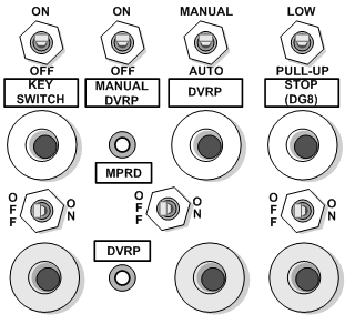
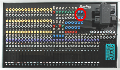
- KEY SWITCH: The KEY SWITCH interface includes a top, vertical-direction ON/OFF switch, which connects directly to the key-switch (ECUP) input to the ECM, to turn the ECM key-switch on/off. The other, side-to-side switch enables/disables the ON/OFF function of the top switch. The red jack allows connection of an external key-switch input. Note: Some ECMs use the key-switch input, others do not. Refer to the datasheet for your ECM.
- MANUAL/DVRP: You can turn the DVRP to the ECM on/off via the MANUAL/DVRP ON/OFF switch, if the DVRP switch (below) is set to MANUAL. The other, side-to-side switch enables/disables the ON/OFF function of the top switch.
- DVRP: You can turn the MANUAL DVRP on/off via the DVRP ON/OFF switch. When the switch is OFF, the DRVP power is automatically supplied. When ON, use of the MANUAL DVRP ON/OFF switch controls the DVRP power.
- LEDs: The MPRD indicator LED is ON when MPRD power is ON (as a result of turning on the ECM). The DVRP indicator LED in ON to indicate the DVRP power to the ECM is ON.
- STOP (DG8): The STOP interface includes a top, vertical-direction LOW/PULL-UP, which connects directly to the E-STOP input to the ECM (the DG8 input acts as a STOP input on the 128-pin ECM). The other, side-to-side switch enables/disables the ON/OFF function of the top switch. The red jack allows connection of an external STOP input.
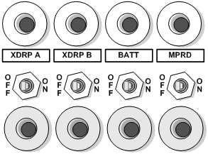
- XDRP A/B: The two XDRP jacks, A and B, each include a side-to-side ON/OFF switch, which turns the respective transducer power on/off.
- BATT: You can turn the battery power to the ECM on/off via the BATT ON/OFF switch.
- MPRD: You can turn the power to the main power relay driver on/off via the MPRD ON/OFF switch.
- LEDs: (see drawing above) The MPRD indicator LED is ON when MPRD power is ON (as a result of turning on the ECM). The DVRP indicator LED in ON to indicate the DVRP power to the ECM is ON.
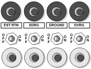
- EST RTN: The EST RTN input provides connection to the EST return resource on the connected ECM. You can connect or disconnect the EST return to the ECM via the EST RTN ON/OFF switch.
- XDRG: You can connect or disconnect the transducer ground to the ECM via the XDRG ON/OFF switch.
- GROUND: You can connect or disconnect the power ground to the ECM via the GROUND ON/OFF switch.
- DVRG: You can connect or disconnect the driver ground to the ECM via the DVRG ON/OFF switch.
Communications
The Simulator supports connecting up to three CAN channels and an RS-485 channel. The jacks are located at the right side of the Simulator just below the junction box and above the harness connector. Each connection includes an OFF/ON switch to disable/enable the channel connection.
Output Sections
These outputs connect to your ECM output pins by designation and in order of resource number. Refer to the datasheet for your particular ECM for resources available. Depending on the resources of the particular ECM in use, some of the Simulator output jacks may not be in use.

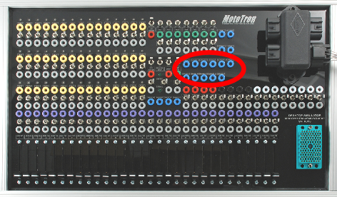
- LEDs: The LEDs above the outputs show status; LEDs turn on green if a low-side output is active and set up as “low-side,” for example, and show red if the output is active as “high-side.”
- ON/OFF: You can turn the output on/off via the switch. When off, the yellow (top) jack is inactive; the monitor (gray) jack is usable with the switch in either the ON or OFF position.
- Output jacks: The top jack (yellow) of each output directly connects to the respective ECM output resource. Output characteristics of the respective ECM resource are thus conveyed.
The lower (gray) jacks are the respective voltage-level monitors only.
Low-Side Outputs
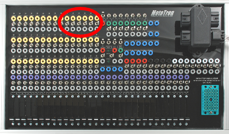
Labeled LSO1-LSO8, eight low-side outputs are located in the upper left corner of the Simulator.
INJ Outputs
Labeled INJ1-INJ12, twelve fuel injector outputs are located at the left side of the Simulator.
EST Outputs
Labeled EST1-EST16, the 16 electronic spark timing outputs are located at the left side of the Simulator. Note: In order to see EST firing indications, turn the respective EST LED ON/OFF switch to OFF.
H-Bridge Outputs
Labeled H1+, H1-, H2+, H2-, H3+ and H3-, the six H-bridge connections are located at the top center of the Simulator.
Analog/Digital Input Sections
Analog Inputs
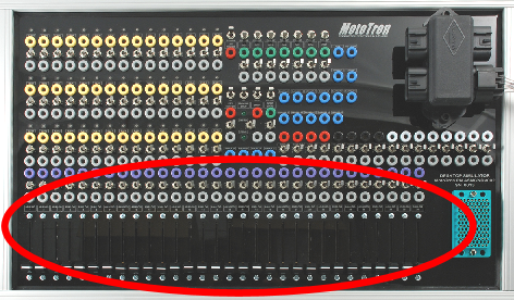
Labeled Analog 1 through Analog 30, the analog inputs (switchable - On/Off) are located along the bottom of the simulator, together with dedicated potentiometer sliders, 0-5V. Note: To connect your own sensor, use the gray jack and switch the corresponding ON/OFF switch to OFF.

Digital Inputs
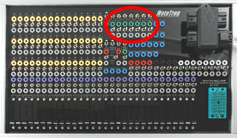
The Simulator supports up to seven digital inputs, labeled DG1-DG7. The jacks are located at top center of the Simulator.
The digital inputs each have a switch for setting input to low or pull-up, along with ON/OFF switches.

- LOW/PULL-UP: Switch input as needed for either pull-down or pull-up connection.
- Input jacks: The top jack (green) of each output directly connects to the respective ECM input resource.
- ON/OFF: You can turn the input on or off via the switch. When off, the green (top) jack is inactive; the monitor (gray) jack is usable with the switch in either the ON or OFF position.
Knock Sensor Inputs
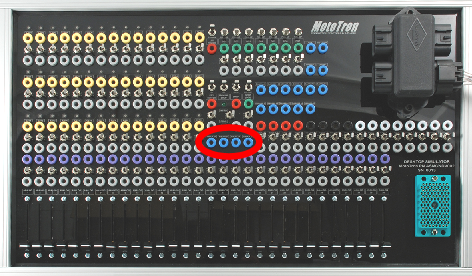
Labeled Knock0 -/+ and Knock1 -/+, the four knock sensor connector jacks are located in the center of the Simulator. There are no associated switches or monitors; user must supply the knock input signal to the Simulator.
CAM/Crank Inputs
The four CAM and Crank inputs are located at the top of the Simulator, labeled CAM and DG CAM, and Crank+/-. There are no associated switches or monitors; user must supply the respective sensor input signal to the Simulator.
Miscellaneous Non-Assigned Jacks
There are 11 non-assigned jacks, reserved for future assignment.
Simulator Harnesses
Get the appropriate harness for the ECM in use. Note, these are not available in the webstore but only by contacting sales@neweagle.net.
| Harness # | ECM Family |
| HARNINTR023A | To 24-Pin - GCM0565024/ECM0S12024 (ISDL/SECM) |
| HARNINTR023B | To 24-Pin - GCM0S12024 (MCHI/MSIM/SMUX) |
| HARNINTR024A | To 48-Pin - ECM0555048 |
| HARNINTR024B | To 48-Pin - ECM0563048 |
| HARNINTR024C | To 48-Pin - GCM0563048/HCM0563048 (FIRE 48) |
| HARNINTR025A | To 80-Pin - ECM0555080 |
| HARNINTR026A | To 112-Pin - ECM555x112 |
| HARNINTR027A | To 128-Pin - ECM0565128 |
Connect the required harness to the harness connector on the Simulator.
