Foundation Block Set: Difference between revisions
No edit summary |
No edit summary |
||
| (30 intermediate revisions by 6 users not shown) | |||
| Line 1: | Line 1: | ||
The Controls Foundation Block set is a library of common control elements. This contains different types of control loop blocks, integrator, filters, etc. These blocks have been designed to work in an embedded environment so they can be used with Raptor or MotoHawk. These blocks are the foundation of any controls model and can be re-used for many applications. | |||
To get more information about this library contact [http://www.neweagle.net/contact.html New Eagle]. | |||
===First Time Block:=== | ===First Time Block:=== | ||
| Line 25: | Line 28: | ||
This block detects a falling edge and outputs a value when it does so. | This block detects a falling edge and outputs a value when it does so. | ||
=== | ===Derivitive:=== | ||
[[image:Derivitive.PNG| Derivitive]] | [[image:Derivitive.PNG| Derivitive]] | ||
| Line 61: | Line 64: | ||
When the divisor is less than the numerator or zero, saturate and output one. | When the divisor is less than the numerator or zero, saturate and output one. | ||
===Integrator=== | ===Integrator:=== | ||
[[image:Integrator.PNG| Integrator]] | [[image:Integrator.PNG| Integrator]] | ||
| Line 73: | Line 76: | ||
The simple PI, PD, and PID block set allows a user to quickly implement basic control loops. | The simple PI, PD, and PID block set allows a user to quickly implement basic control loops. | ||
===The Universal PI, PD, and PID Blocks=== | ===The Universal PI, PD, and PID Blocks:=== | ||
[[image: | [[image:Universal_controllers.PNG| Universal Controllers]] | ||
The Universal PI, PD, PID blocks allow a user to quickly implement many types of control loops. | The Universal PI, PD, PID blocks allow a user to quickly implement many types of control loops. | ||
| Line 85: | Line 88: | ||
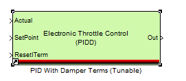
This block helps the user implement a PID with Damper Terms. | This block helps the user implement a PID with Damper Terms. | ||
===Handoff Alpha=== | ===Handoff Alpha:=== | ||
[[image:Handoff_Alpha.PNG| Handoff Alpha]] | [[image:Handoff_Alpha.PNG| Handoff Alpha]] | ||
| Line 91: | Line 94: | ||
The Handoff Alpha block converts a boolean input signal to a more slowly ramping 'alpha' from 0 to 1. | The Handoff Alpha block converts a boolean input signal to a more slowly ramping 'alpha' from 0 to 1. | ||
===Triggered and Enabled Counter Rising=== | ===Triggered and Enabled Counter Rising:=== | ||
[[image:Counter_blocks.PNG| Counter blocks]] | [[image:Counter_blocks.PNG| Counter blocks]] | ||
| Line 97: | Line 100: | ||
The triggered and enabled counter count set up an increment. The triggered block does it on the rising edge of a signal, and the enabled block does it when it is enabled. | The triggered and enabled counter count set up an increment. The triggered block does it on the rising edge of a signal, and the enabled block does it when it is enabled. | ||
===Variable Rate Limiter=== | ===Variable Rate Limiter:=== | ||
[[image:Variable_Rate_Limiter.PNG| Variable Rate Limiter.]] | [[image:Variable_Rate_Limiter.PNG| Variable Rate Limiter.]] | ||
| Line 107: | Line 110: | ||
[[image:Decayed_First_Order_Filter.PNG| Decayed first Order]] | [[image:Decayed_First_Order_Filter.PNG| Decayed first Order]] | ||
The decayed First-Order Filter decays from the Initial Value to the Final Value when enabled. | The decayed First-Order Filter decays from the Initial Value to the Final Value when enabled. | ||
==Calibratable Foundational Operations== | ==Calibratable Foundational Operations== | ||
===Polynomial Tunable=== | ===Polynomial (Tunable)=== | ||
[[image:Polynomial_Tunable.PNG| Polynomial Tunable]] | [[image:Polynomial_Tunable.PNG| Polynomial Tunable]] | ||
| Line 117: | Line 120: | ||
The Polynomial Tunable block allows the user to evaluate a polynomial using Horner’s Rule. The Polynomial is entered using a calibration block in the subsystem. | The Polynomial Tunable block allows the user to evaluate a polynomial using Horner’s Rule. The Polynomial is entered using a calibration block in the subsystem. | ||
===The Tunable 1st Order Low-Pass Filter=== | ===The Tunable 1st Order Low-Pass Filter:=== | ||
[[image:First_Order_Low_Pass_Tunable.PNG| First Order Low Pass Tunable]] | [[image:First_Order_Low_Pass_Tunable.PNG| First Order Low Pass Tunable]] | ||
| Line 123: | Line 126: | ||
This is the 1st-Order Low-Pass filter with extra logic to have the alpha be a fraction of dT. If the calibration value for FilConst is lower than dT than the alpha value is one. If FiltConst is greater than dT, than the alpha is the dT divided FiltConst. | This is the 1st-Order Low-Pass filter with extra logic to have the alpha be a fraction of dT. If the calibration value for FilConst is lower than dT than the alpha value is one. If FiltConst is greater than dT, than the alpha is the dT divided FiltConst. | ||
===Saturation Tunable=== | ===Saturation (Tunable):=== | ||
[[image:Saturation_tunable.PNG| Saturation tunable]] | [[image:Saturation_tunable.PNG| Saturation tunable]] | ||
| Line 129: | Line 132: | ||
This is the Saturation Block with the upper and lower limits as calibration values to be used in MotoTune. | This is the Saturation Block with the upper and lower limits as calibration values to be used in MotoTune. | ||
===Universal PD Tunable=== | ===Universal PD (Tunable):=== | ||
[[image:Universal_PD_Tunable.PNG| Universal PD Tunable]] | [[image:Universal_PD_Tunable.PNG| Universal PD Tunable]] | ||
| Line 135: | Line 138: | ||
This block is the Universal PD block with many of inputs and outputs as Calibration and Probe blocks to be used in MotoTune. | This block is the Universal PD block with many of inputs and outputs as Calibration and Probe blocks to be used in MotoTune. | ||
===Universal PID Tunable=== | ===Universal PID Tunable:=== | ||
[[image:Universal_PID_(Tunable).PNG| Universal PID (tunable)]] | [[image:Universal_PID_(Tunable).PNG| Universal PID (tunable)]] | ||
| Line 141: | Line 144: | ||
This block is the Universal PID Controller with many of the Inputs and outputs set as Calibration and Probe values to be used in MotoTune. | This block is the Universal PID Controller with many of the Inputs and outputs set as Calibration and Probe values to be used in MotoTune. | ||
===PID with Damper Terms Tunable=== | ===PID with Damper Terms (Tunable):=== | ||
[[image:PID_with_damper_terms_(tunable).PNG| PID with damper terms (tunable)]] | [[image:PID_with_damper_terms_(tunable).PNG| PID with damper terms (tunable)]] | ||
| Line 147: | Line 150: | ||
This block is the Universal PIDD controller with many of the inputs and outputs set as Calibration and Probe blocks. | This block is the Universal PIDD controller with many of the inputs and outputs set as Calibration and Probe blocks. | ||
===Universal PD Tunable and Scheduled=== | ===Universal PD (Tunable and Scheduled):=== | ||
[[image:Universal_PD_tunable_and_Scheduled.PNG| Universal PD (tunable and scheduled)]] | [[image:Universal_PD_tunable_and_Scheduled.PNG| Universal PD (tunable and scheduled)]] | ||
| Line 153: | Line 156: | ||
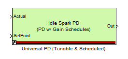
This block takes the universal PD block and has many of the inputs and outputs set as Calibration and Probe blocks to be used in MotoTune. It also has lookup tables to schedule the signals. | This block takes the universal PD block and has many of the inputs and outputs set as Calibration and Probe blocks to be used in MotoTune. It also has lookup tables to schedule the signals. | ||
===Universal PID Tunable and Scheduled=== | ===Universal PID (Tunable and Scheduled):=== | ||
[[image:Universal_PID_(tunable_&_Scheduled).PNG| Universal PID (tunable and scheduled)]] | [[image:Universal_PID_(tunable_&_Scheduled).PNG| Universal PID (tunable and scheduled)]] | ||
| Line 159: | Line 162: | ||
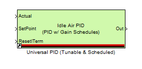
This block takes the universal PID block and has many of the inputs and outputs set as Calibration and Probe blocks to be used in MotoTune. It also has lookup tables to schedule the information. | This block takes the universal PID block and has many of the inputs and outputs set as Calibration and Probe blocks to be used in MotoTune. It also has lookup tables to schedule the information. | ||
===PWM Generator=== | ===PWM Generator:=== | ||
[[image:PWM_Generator.PNG| PWM Generator]] | [[image:PWM_Generator.PNG| PWM Generator]] | ||
| Line 165: | Line 168: | ||
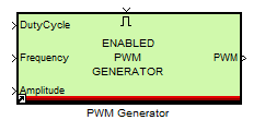
The PWM Generator block uses the dT module block to use dT to create a PWM signal to be used on a module. | The PWM Generator block uses the dT module block to use dT to create a PWM signal to be used on a module. | ||
===Hysteresis=== | ===Hysteresis:=== | ||
[[image:Hysterisis.PNG| Hysterisis]] | [[image:Hysterisis.PNG| Hysterisis]] | ||
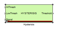
The Hysteresis block takes an inputted signal and an upper and lower bound. It then induces hysteresis in the signal. | The Hysteresis block takes an inputted signal and an upper and lower bound. It then induces hysteresis in the signal. | ||
==More Information== | |||
For more information, do not hesitate to contact us at '''[mailto:support@neweagle.net support@neweagle.net]'''. | |||
==Webstore== | |||
This library was designed for embedded applications and contains the foundational blocks for a controls model including closed loop control blocks, filters, and other useful functions. | |||
:*'''[http://store.neweagle.net/products-by-tools/motohawk-tools/new-eagle-motohawk-libraries/motohawk-foundation-block-set.html Webstore: Foundation Block Set]''' | |||
[ | |||
Latest revision as of 13:59, 31 July 2024
The Controls Foundation Block set is a library of common control elements. This contains different types of control loop blocks, integrator, filters, etc. These blocks have been designed to work in an embedded environment so they can be used with Raptor or MotoHawk. These blocks are the foundation of any controls model and can be re-used for many applications.
To get more information about this library contact New Eagle.
First Time Block:
The first time block sends a true signal out the first time the subsystem it is in is triggered. All other executions of that subsystem will have this block output a false signal.
Compare To:
The Compare To block allows the user to compare an inputted value vs. the given value in the mask. It will output a true signal when the values match.
Rising Edge:
This block detects a rising edge and sends out a value 1 when it does so.
Falling Edge:
This block detects a falling edge and outputs a value when it does so.
Derivitive:
This block takes the derivate of an inputted signal.
Saturation:
The saturation block takes a min, max and inputted value. It then outputs the inputted signal when it is between the min max. When the inputted signal goes over the boundaries it outputs the min or max values.
First Order Low Pass:
The 'alpha' input is T/t. So when alpha = 1, the block simply passes the input through to the output, and when alpha = 0, the block forever holds its last output value.
Median Filter:
This filter block stores the number of data points that the user requests and gives the median of those values.
Time Since Enabled:
The Time Since Enabled block outputs the amount of time that has elapsed since the enable input has gone high. It holds its value when the enable input goes low, but resets again when it goes high.
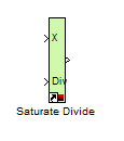
Saturate Divide:
When the divisor is less than the numerator or zero, saturate and output one.
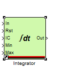
Integrator:
The integrator block takes an incoming signal and integrates it. You can set a Min and Max value for the output. You can also enable the signal with the Rst signal, and it will output the IC value.
Simple PI, PD, and PID Blocks:
The simple PI, PD, and PID block set allows a user to quickly implement basic control loops.
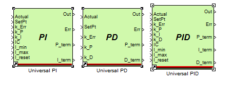
The Universal PI, PD, and PID Blocks:
The Universal PI, PD, PID blocks allow a user to quickly implement many types of control loops.
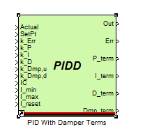
PID With Damper Terms:
This block helps the user implement a PID with Damper Terms.
Handoff Alpha:
The Handoff Alpha block converts a boolean input signal to a more slowly ramping 'alpha' from 0 to 1.
Triggered and Enabled Counter Rising:
The triggered and enabled counter count set up an increment. The triggered block does it on the rising edge of a signal, and the enabled block does it when it is enabled.
Variable Rate Limiter:
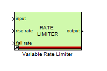
The variable rate Limiter allows the user to dampen an incoming signal by limiting its rate of change in one time step.
Decayed First Order Filter:
The decayed First-Order Filter decays from the Initial Value to the Final Value when enabled.
Calibratable Foundational Operations
Polynomial (Tunable)
The Polynomial Tunable block allows the user to evaluate a polynomial using Horner’s Rule. The Polynomial is entered using a calibration block in the subsystem.
The Tunable 1st Order Low-Pass Filter:
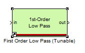
This is the 1st-Order Low-Pass filter with extra logic to have the alpha be a fraction of dT. If the calibration value for FilConst is lower than dT than the alpha value is one. If FiltConst is greater than dT, than the alpha is the dT divided FiltConst.
Saturation (Tunable):
This is the Saturation Block with the upper and lower limits as calibration values to be used in MotoTune.
Universal PD (Tunable):
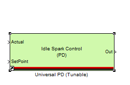
This block is the Universal PD block with many of inputs and outputs as Calibration and Probe blocks to be used in MotoTune.
Universal PID Tunable:
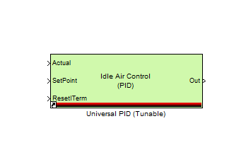
This block is the Universal PID Controller with many of the Inputs and outputs set as Calibration and Probe values to be used in MotoTune.
PID with Damper Terms (Tunable):
This block is the Universal PIDD controller with many of the inputs and outputs set as Calibration and Probe blocks.
Universal PD (Tunable and Scheduled):
This block takes the universal PD block and has many of the inputs and outputs set as Calibration and Probe blocks to be used in MotoTune. It also has lookup tables to schedule the signals.
Universal PID (Tunable and Scheduled):
This block takes the universal PID block and has many of the inputs and outputs set as Calibration and Probe blocks to be used in MotoTune. It also has lookup tables to schedule the information.
PWM Generator:
The PWM Generator block uses the dT module block to use dT to create a PWM signal to be used on a module.
Hysteresis:
The Hysteresis block takes an inputted signal and an upper and lower bound. It then induces hysteresis in the signal.
More Information
For more information, do not hesitate to contact us at support@neweagle.net.
Webstore
This library was designed for embedded applications and contains the foundational blocks for a controls model including closed loop control blocks, filters, and other useful functions.


