MotoHawk Hardware: Difference between revisions
| (67 intermediate revisions by 7 users not shown) | |||
| Line 1: | Line 1: | ||
{{Navigation}} [[MotoHawk-Platform|MotoHawk Platform]] > [[MotoHawk]] > '''MotoHawk Hardware''' | |||
== MotoHawk (formerly called MotoTron) Line of Controllers and Specifications == | == MotoHawk (formerly called MotoTron) Line of Controllers and Specifications == | ||
Please visit the following '''[http://www.neweagle.net/support/wiki/docs/Datasheets/ECUSummary.pdf MotoHawk ECU Summary Page]''' for MotoHawk controller family availability. This is a good starting point to help select a family for | Please visit the following '''[http://www.neweagle.net/support/wiki/docs/Datasheets/ECUSummary.pdf MotoHawk ECU Summary Page]''' for MotoHawk controller family availability. This is a good starting point to help select a family for your project. More information about the families, including part numbers and purchase links, can be found on the '''[[Controllers#MotoHawk_Modules|Controllers]]''' page. | ||
===RoHS and MotoTron ECU Modules === | ===RoHS and MotoTron ECU Modules === | ||
Motorola had been pushing for RoHS compliance across the company since they | Motorola had been pushing for RoHS compliance across the company since they were mainly consumer products, but when Conti took over, there ceased to be a push for that. Visteon and Conti do not plan to go lead-free on solder — the impact to the part design and manufacturing (higher reflow temps) is too great. | ||
=== Controller Quality Certification === | === Controller Quality Certification === | ||
Both Visteon and Continental built MotoHawk modules (24, 48, 80, 128 pin modules) have QS-9000/TS16949 quality certification. | Both Visteon- and Continental-built MotoHawk modules (24-, 48-, 80-, 128-pin modules) have QS-9000/TS16949 quality certification. | ||
=== Do MotoHawk ECUs meet J1455 Heavy Duty Truck Standards? === | === Do MotoHawk ECUs meet J1455 Heavy-Duty Truck Standards? === | ||
In general, J1455 is a guideline, not | In general, J1455 is a guideline, not a standard. A potential OEM customer has to provide specific details on some tests called out in J1455. For vibration, some profiles are provided in the standard, but the OEM has to determine the acceleration factors and duration based upon their expected system usage. | ||
MotoHawk ECUs including the ECM24, GCM24, GCM48 | MotoHawk ECUs including the ECM24, GCM24, ECM48 and GCM48 have been used in heavy-duty truck applications for CAN gateways and diesel emissions controls. In many cases, a customer will request and pay for additional testing than what was done in the validation of a MotoHawk module at either Continental or Visteon. | ||
=== Which label contains the serial number? === | === Which label contains the serial number? === | ||
| Line 24: | Line 21: | ||
===Module Selection=== | ===Module Selection=== | ||
Contact our '''[mailto:sales@neweagle.net sales team]''' for assistance in selecting the correct module for your project. | |||
===Use of MPRD=== | ===Use of MPRD=== | ||
In all development harnesses New Eagle provides | In all development harnesses New Eagle provides and would design, we include a main power relay, an example of which can be seen in the fusing requirements diagram below. The relay takes power from the battery and is controlled by the MPRD pin to provide power to the output pins through the DRVP pins. This might seem redundant and, instead of having the relay, you could just hardwire DRVP pins to the battery source; however, for most applications, this is not a good idea. One useful function of the main power relay (MPR) sourcing all the power that is sunk by the low-side drivers (including injector drivers) is that the ECM can disable actuator power if it determines an actuator is shorted out on the control side to chassis ground. Of course, this disables all low-side drivers, but it is the compromise to avoid having more expensive high-side drivers on the hardware, which would be able to disable source to the actuators individually. The assumption here is that shorts to battery power are much rarer than shorts to chassis. | ||
The second reason for the MPR is reverse battery protection | The second reason for the MPR is reverse battery protection. This architecture allows the low-side drivers, other than MPRD, to not have reverse battery diodes as a form of protection, since if there is no DRVP, there will be no current flow. For this protection, use of the MPR is mandatory. Anything engine-related would typically go through the MPR. In cases where this is not convenient, like on a bus with the engine in the rear, dash lamps and such would be sourced from VBAT. If you have a question on which LSDs have a blocking diode, look at the datasheet. If the datasheet does not contain the information, please contact New Eagle. However, as mentioned, it is a better practice to use MPR and to only use the blocking diode when necessary. If you do hook up the low-side drivers in a reverse-battery situation, all the loads will be actuated, and it will likely damage the ECU if the condition persists. | ||
===Fusing Requirements=== | ===Fusing Requirements=== | ||
The load fusing requirements are dependent on the application | The load fusing requirements are dependent on the application and module. An example diagram of how to fuse a module harness is below. However, across the range of modules, a 2A fuse for the battery and 1A for KEY_SW is recommended. The DRVP feed to the module is fused in common with the MPR coil feed and the size will depend on what outputs are being used. DRVP feeds the H-bridges and LSO recirculating current. It is also good practice to fuse injectors, ignition coils and miscellaneous with separate fuses. The diagram shows separate relays as well as fuses for the injector inputs, but this is not required as long as the relay current for MPRD is not exceeded. It is important to fuse the DRVP to the module separately from the injector feed, as field issues have occurred where a common fuse blew, and the injectors were back fed via the LSO recirculating diodes and still fired but at a reduced performance. This diagram shows separate relays as well, but this is not required as long as the relay current is not exceeded. | ||
[[File:Fusing_requirements_75.png ]] | [[File:Fusing_requirements_75.png ]] | ||
== | ===Knock Calibration=== | ||
Detailed knock calibration instructions are provided upon request. | |||
=== | ==General Hardware/Wiring Questions== | ||
===ECUP vs Key_SW and ESTOP=== | |||
'''What/where is the ECUP line (in reference to key-switch operation)? I cannot see it in the wiring diagram for the controller or for the development harness. I do, however, see "KEY_SW" and "STOP-DIG/AN_IN", which are connected to the SmartCraft connector as "WAKE" and "ESTOP" respectively. Or is the main power input line affected by the operation of the key-switch, and that in turn allows the controller to shut down properly?''' | |||
:ECUP and KEY_SW are used interchangeably. Different modules use the two terms, but they always mean the same thing. ECUP or KEY_SW are monitored by the internal power conditioning to wake up the processor. Once the processor is up and online, the application software monitors this line to indicate when to do a shutdown of the processor. On modules that have a BATT line, the module is capable of achieving a controlled shutdown by drawing power from the BATT line until a graceful shutdown is achieved. | |||
:Basically, the sequence of events is that once the ECUP line drops, we begin an orderly shutdown of the application which includes storing non-volatile memory and shutting off the actuators, including the main power relay output. Once the MPR is dropped, the module will either go dormant or reboot depending upon the voltage at the ECUP/KEY_SW line. | |||
'''I tried to operate the controller by unplugging the key-switch and switching power directly, but the controller did not operate. Is this what you would expect? Is this related to the above question?''' | |||
:Yes. KEY_SW is the turn on/turn off signal. | |||
===Operating Without Key-Switch=== | |||
'''If I wanted to operate the controller without the key-switch (assuming I don't need to save any non-volatile memory prior to loss of power), would it be appropriate to connect/wire up the pins as if the switch were in the "on" position? If so, can you please provide the pin assignments and states for the switch? (When in on-mode, does it connect power to wake?)''' | |||
:Wire BATT, KEY_SW and DRVP pins to your voltage source. The module will boot up on the power coming up and crash when power goes down. | |||
'''Is it possible and/or appropriate to replace the key-switch with a relay or small manual switch between the pins identified in the above question?''' | |||
:Yes. You can switch ECUP or all of the power through a switch or relay. | |||
=== | ===SmartCraft Pinout=== | ||
[[Image:SmartCraft pinout.jpg|center]] | |||
==== | ===DB9 Pinout=== | ||
[[Image:DB9-CAN-pinout.jpg|center]] | |||
== | ===Boot Key Recovery=== | ||
When working in the prototype phase with newly created *.srz files from MotoHawk, it is possible to program an *.srz with errors in the CAN software or in the model that prevent communications with the module once programmed. When this happens, the module appears to be locked up or frozen when accessing the module via MotoTune. In this case, use the boot key to force the module into reboot mode such that a known, valid *.srz can be reprogrammed into the module. | |||
====Understanding Boot Key Functionality==== | |||
The boot key has a 10-pin CAN connector that should be inserted into an open port on the CAN junction box. The device generates a 555 Hz, 5V signal out of pin E when power is applied to pin A and ground applied to pin B. | |||
At power-on, the hardboot loader for the module first looks to see if the boot key input or boot cable sequence is present. If so, the code prepares to accept programming. If no programming instructions are received from MotoTune within a few seconds (~3), then the existing program application is started, and recovery is not successful. At power-on (BATT and KEY_SW), if the hardboot loader does not detect the boot key signal (or boot harness sequence), then the hardboot loader skips the three-second wait and starts the existing application. So, the ECU must see the boot key signal immediately when it powers up. | |||
'''''Note:''' It can help, especially on the 112-pin modules, to energize the boot key before the module (you may need to disconnect the connector between ECU and the junction box but leave power to junction box).'' | |||
The recovery procedure is as follows: | The recovery procedure is as follows: | ||
1. Plug the | 1. Plug the boot key into the junction box and make sure that power and ground are connected to pins A and B on the junction box. Connect pin E of the junction box to the channel listed below on the following modules. | ||
*ECM-555-48 – ESTOP | *ECM-555-48 – ESTOP | ||
*ECM-555-80 – ESTOP | *ECM-555-80 – ESTOP | ||
*PCM-565-128 – DG1 | *PCM-565-128 – DG1 | ||
*HCM-563-48 – STOP | *HCM-563-48 – STOP | ||
*GCM-563-48 – STOP* | *GCM-563-48 – STOP | ||
**If the boot key fails to work with the above two GCM/HCM 563-48 modules, refer to '''[http://www.neweagle.net/support/wiki/docs/Other/48HardBootRecovery/Fire48HardbootRecoveryDocument.pdf Fire48 Hardboot Recovery]'''. In order to purchase a boot cable, visit '''[https://store.neweagle.net/shop/products/connectors-tools/harnesses-connectors-connectors-tools/for-motohawk-controllers-harnesses-connectors-connectors-tools/boot-cable-gcm-563-48/ HARN-ECM-022]''' | |||
**When using the boot key with the GCM/HCM48, power must be applied to the boot key before power is applied to the module, because the boot up procedure on those modules is so quick that, otherwise, the boot procedure will be over before the boot key can send the signal. We've found the boot harness to be a more reliable way to boot those modules. | |||
*ECM-5554-112 – STOP | *ECM-5554-112 – STOP | ||
*HCS-12 (24 pin modules) - Refer to '''[http://www.neweagle.net/support/wiki/docs/Other/hcs12bootcable.pdf HCS12 Boot Connections for GCM 24 | *HCS-12 (GCM 24-pin modules) - Refer to '''[http://www.neweagle.net/support/wiki/docs/Other/hcs12bootcable.pdf HCS12 Boot Connections for GCM 24-Pin Module]''' | ||
*SECM24 | |||
** Tie pins 1, 4 and 15 together | |||
** Tie pins 3, 5, 17 and 18 together (and pin 16 on the SECM24-0804) | |||
** Tie pin 13 to battery power | |||
** Tie pin 14 to battery ground | |||
** Tie pin 6 to CAN+ and pin 19 to CAN- | |||
*ECM-OH main core - DG8 | |||
** Note: The ECM-OH is programmed at the factory with a sample application that sets CAN-1 of both the Main and Auxiliary Cores to 500K baud rate. Both cores are internally connected within the ECU on CAN-1. If the baud rate of one of the cores is changed on CAN-1, then the baud rate of the other core must be programmed to match CAN-1. | |||
** For programming the ECM-OH, it may help to think of it as two modules connected on CAN-1: the main and the aux S12G. Since the cores are internally connected on CAN-1, the baud rate must be the same for both on CAN-1, and they must have different city IDs. The module ships pre-programmed with an application that sets the baud rate for both cores to 500K, with the city ID of main as 0xB and the city ID of the aux as 0x81. | |||
** The hardboot (the settings used to program the module by boot key or boot harness) if it needs to be recovered is:<br> Main: <br>250K b/s <br>City ID 0xB<br> Aux:<br> 250K b/s <br>City ID 0x81 | |||
** To change the baud rate on CAN-1, first program the main core. Cycle power to put auxiliary in hardboot, then program the auxiliary as above. | |||
*ECM-563-48 – '''Does not use a boot key.''' | *ECM-563-48 – '''Does not use a boot key.''' | ||
**There are two approaches to recovering the module: | |||
**#Use a Boot Cable (p/n HARN-ECM-013), purchased at '''[https://store.neweagle.net/shop/products/connectors-tools/harnesses-connectors-connectors-tools/for-motohawk-controllers-harnesses-connectors-connectors-tools/boot-and-quick-programming-cable-for-ecm-563-48/ HARN-ECM-013]'''. Download the drawing from '''[[Harness Documentation]]'''. | |||
**#To boot strap the ECM-563-48 modules, connect the following channels and follow the steps below.<br>AN1 – AN6 Pull to +5V<br>AN8 Pull to GND<br>AN11 - AN12 Pull to +5V | |||
*ECM-S12X-70-1001 - '''Does not use a boot key.''' | |||
::* | **There are two approaches to recovering the module: | ||
**#Use the Programming Harness (p/n HARN-ECM-029), purchased at '''[https://store.neweagle.net/shop/products/connectors-tools/harnesses-connectors-connectors-tools/for-motohawk-controllers-harnesses-connectors-connectors-tools/harness-ecm70-programming/ HARN-ECM-029]'''. | |||
**#In addition to battery power, ground, key-switch and CAN+/-, connect the following channels before programming:<br>Tie AN02, AN03 and AN07 to XDRGND1<br>Tie AN01, AN04, AN05 and AN06 to XDRPWR1<br>Battery power to DRVP1 | |||
2. With the power to the module off and the boot key installed, select a known, valid .srz file to flash onto the module and program the module at 250kbps on the module's default city | 2. With the power to the module off and the boot key installed, select a known, valid *.srz file to flash onto the module and program the module at 250kbps on the module's default city ID. All modules default to city ID PCM-1 (0x0B) with the following exceptions: | ||
*ECM-S12 - SECM-1 (0x81) (Not applicable to ECM-S12-24-0804, which defaults to PCM-1) | |||
*GCM-S12 - uCHI-1 (0x91) | |||
3. When the “Looking for an ECU” prompt appears in the dialogue box, turn on power to the ECU. The module must “wake-up” with the boot key applied in order to force a reboot. | 3. When the “Looking for an ECU” prompt appears in the dialogue box, turn on power to the ECU. The module must “wake-up” with the boot key applied in order to force a reboot. | ||
| Line 133: | Line 121: | ||
===Voltage Specifications for Modules=== | ===Voltage Specifications for Modules=== | ||
While all the modules are designed to withstand momentary short-to-battery on the input sensor pins (except those that inherently cannot be protected), the hardware validation test is typically | While all the modules are designed to withstand momentary short-to-battery on the input sensor pins (except those that inherently cannot be protected), the hardware validation test is typically one minute short-to-battery. | ||
In the case of analog and digital inputs (nominal | In the case of analog and digital inputs (nominal 5V), the circuit may not be able to dissipate heat when connected to a higher voltage on a longer timeframe. For instance, the pull-up or pull-down resistor may not be sized to dissipate heat from that higher voltage (resistor wattage rating). | ||
+++++ | +++++ | ||
| Line 141: | Line 129: | ||
For the circuits marked "16V okay" in the table below, the resistor wattage rating is such that continuous operation at 16V should be okay. | For the circuits marked "16V okay" in the table below, the resistor wattage rating is such that continuous operation at 16V should be okay. | ||
"Double Battery" situation: | "Double Battery" situation: At nominal 24V (as high as 32V jumpstart), the trace widths as well as the PU/PD resistor may be vulnerable. Some of the pull-downs would likely be okay, but this should be verified. For example, AN4: 220kΩ pull-down ---> P = (V^2) / R = (32*32) / (220e3) = 0.005 W = 5 mW. The resistor for AN4 is rated 63 mW. Depending on ambient temperature for the module (heat transfer from the resistor, module body type, ambient temperature), this circuit may be okay for short "double battery" exposure. | ||
[[Image:Chart_2.JPG|center]] | [[Image:Chart_2.JPG|center]] | ||
===H- | ===H-Bridge Wiring=== | ||
The H-bridge is normally wired as: | The H-bridge is normally wired as: | ||
(H+)----(load)----( | |||
(H+)----(load)----(H-) | |||
and the H-bridge circuit is powered from DRVP internally. | and the H-bridge circuit is powered from DRVP internally. | ||
(BATT)----(MPR Common, MPR Normally Open)----(DRVP)----(to H-bridge and other internal devices | |||
(BATT)----(MPR Common, MPR Normally Open)----(DRVP)----(to H-bridge and other internal devices and flyback diodes). | |||
The low side of the H-bridge circuitry connects to DRVGx and then back to battery ground. | The low side of the H-bridge circuitry connects to DRVGx and then back to battery ground. | ||
In one H-bridge, the fault/current feedback line is shared between each half bridge. Therefore, you can only get reliable fault or current data when using it as | In one H-bridge, the fault/current feedback line is shared between each half bridge. Therefore, you can only get reliable fault or current data when using it as an H-bridge or using one half bridge only. If both half-bridges are used independently, the fault/current feedback line will provide unreliable data for either of them. | ||
===CAN Addressing Conflicts=== | ===CAN Addressing Conflicts=== | ||
{{:MotoTune Conflict}} | {{:MotoTune Conflict}} | ||
===Implementing J1587 Protocol on a J1708 | ===Implementing J1587 Protocol on a J1708 Hardware Layer (using a MotoTron RS485 Driver)=== | ||
An RS485 software driver in MotoHawk can be written for J1587. The hardware signal conditioning and some general J1587 notes follow: | |||
[[Image:PhysProp.JPG]] | [[Image:PhysProp.JPG]] | ||
[[Image:QFacts.JPG]] | [[Image:QFacts.JPG]] | ||
====Communication | ====Communication Between Serial Port on ECU and USB Device Over RS485==== | ||
Let's assume you want to use the USB with a laptop/PC and enable Mototune to communicate over RS485. So, when the hardware is connected to the PC, it would be recognized by the computer, say as COM7 port. | |||
#Add a New Port by going to Motoserver -> Ports -> Add. In the window that appears, select ‘Serial’ under Type and ‘COM7’ under Location. | |||
#‘Serial I/O Blocks’ in the MotoHawk blockset will help define the communication over a specific protocol, RS485 in this case. | |||
===Hall Effect Inputs === | ===Hall Effect Inputs === | ||
| Line 178: | Line 167: | ||
===DC Motor Drive === | ===DC Motor Drive === | ||
Can | Can a MotoHawk module drive a DC Motor? If current is going one way, you can use a low-side drive. You can parallel LSDs to get the power required. For example, a 12V, 150-watt motor would require 12.5 amps of drive. | ||
===S12(X) Recommended Stack Size=== | |||
The '''[[MotoHawk_Resource_Documents|"Working with the S12" Application Document]]''' indicates a stack baseline when starting your application. Below is another recommended stack size if the stack baseline is low in certain areas. This is applicable towards the 24-pin and 70-pin controllers that use the Freescale S12 or S12X processors. | |||
'''Note:''' The following stack sizes are recommendations and should be adjusted according to the application requirements. | |||
[[File:S12_stack.png]] | |||
===Grounding the ECU cases=== | |||
All MotoHawk ECU cases should be mounted through non-conductive vibration isolators and are '''''NOT''''' intended to be externally grounded. They function as an EMI shield and are RC coupled to the PCB ground plane. Grounding the case will not impact the functionality of the unit but may affect the EMC performance and ESD protection. | |||
[[Category:Vendors/Woodward]] | [[Category:Vendors/Woodward]] | ||
Latest revision as of 15:37, 10 March 2023
New Eagle > Products Wiki > MotoHawk Platform > MotoHawk > MotoHawk Hardware
MotoHawk (formerly called MotoTron) Line of Controllers and Specifications
Please visit the following MotoHawk ECU Summary Page for MotoHawk controller family availability. This is a good starting point to help select a family for your project. More information about the families, including part numbers and purchase links, can be found on the Controllers page.
RoHS and MotoTron ECU Modules
Motorola had been pushing for RoHS compliance across the company since they were mainly consumer products, but when Conti took over, there ceased to be a push for that. Visteon and Conti do not plan to go lead-free on solder — the impact to the part design and manufacturing (higher reflow temps) is too great.
Controller Quality Certification
Both Visteon- and Continental-built MotoHawk modules (24-, 48-, 80-, 128-pin modules) have QS-9000/TS16949 quality certification.
Do MotoHawk ECUs meet J1455 Heavy-Duty Truck Standards?
In general, J1455 is a guideline, not a standard. A potential OEM customer has to provide specific details on some tests called out in J1455. For vibration, some profiles are provided in the standard, but the OEM has to determine the acceleration factors and duration based upon their expected system usage.
MotoHawk ECUs including the ECM24, GCM24, ECM48 and GCM48 have been used in heavy-duty truck applications for CAN gateways and diesel emissions controls. In many cases, a customer will request and pay for additional testing than what was done in the validation of a MotoHawk module at either Continental or Visteon.
Which label contains the serial number?
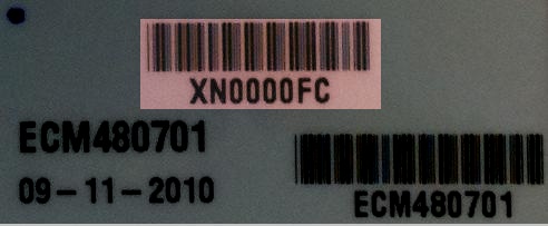
Here is a label applied by Woodward that has the serial number highlighted in red.
Module Selection
Contact our sales team for assistance in selecting the correct module for your project.
Use of MPRD
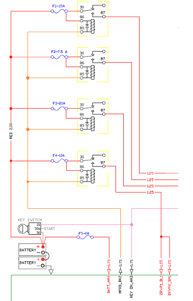
In all development harnesses New Eagle provides and would design, we include a main power relay, an example of which can be seen in the fusing requirements diagram below. The relay takes power from the battery and is controlled by the MPRD pin to provide power to the output pins through the DRVP pins. This might seem redundant and, instead of having the relay, you could just hardwire DRVP pins to the battery source; however, for most applications, this is not a good idea. One useful function of the main power relay (MPR) sourcing all the power that is sunk by the low-side drivers (including injector drivers) is that the ECM can disable actuator power if it determines an actuator is shorted out on the control side to chassis ground. Of course, this disables all low-side drivers, but it is the compromise to avoid having more expensive high-side drivers on the hardware, which would be able to disable source to the actuators individually. The assumption here is that shorts to battery power are much rarer than shorts to chassis.
The second reason for the MPR is reverse battery protection. This architecture allows the low-side drivers, other than MPRD, to not have reverse battery diodes as a form of protection, since if there is no DRVP, there will be no current flow. For this protection, use of the MPR is mandatory. Anything engine-related would typically go through the MPR. In cases where this is not convenient, like on a bus with the engine in the rear, dash lamps and such would be sourced from VBAT. If you have a question on which LSDs have a blocking diode, look at the datasheet. If the datasheet does not contain the information, please contact New Eagle. However, as mentioned, it is a better practice to use MPR and to only use the blocking diode when necessary. If you do hook up the low-side drivers in a reverse-battery situation, all the loads will be actuated, and it will likely damage the ECU if the condition persists.
Fusing Requirements
The load fusing requirements are dependent on the application and module. An example diagram of how to fuse a module harness is below. However, across the range of modules, a 2A fuse for the battery and 1A for KEY_SW is recommended. The DRVP feed to the module is fused in common with the MPR coil feed and the size will depend on what outputs are being used. DRVP feeds the H-bridges and LSO recirculating current. It is also good practice to fuse injectors, ignition coils and miscellaneous with separate fuses. The diagram shows separate relays as well as fuses for the injector inputs, but this is not required as long as the relay current for MPRD is not exceeded. It is important to fuse the DRVP to the module separately from the injector feed, as field issues have occurred where a common fuse blew, and the injectors were back fed via the LSO recirculating diodes and still fired but at a reduced performance. This diagram shows separate relays as well, but this is not required as long as the relay current is not exceeded.
Knock Calibration
Detailed knock calibration instructions are provided upon request.
General Hardware/Wiring Questions
ECUP vs Key_SW and ESTOP
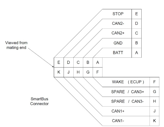
What/where is the ECUP line (in reference to key-switch operation)? I cannot see it in the wiring diagram for the controller or for the development harness. I do, however, see "KEY_SW" and "STOP-DIG/AN_IN", which are connected to the SmartCraft connector as "WAKE" and "ESTOP" respectively. Or is the main power input line affected by the operation of the key-switch, and that in turn allows the controller to shut down properly?
- ECUP and KEY_SW are used interchangeably. Different modules use the two terms, but they always mean the same thing. ECUP or KEY_SW are monitored by the internal power conditioning to wake up the processor. Once the processor is up and online, the application software monitors this line to indicate when to do a shutdown of the processor. On modules that have a BATT line, the module is capable of achieving a controlled shutdown by drawing power from the BATT line until a graceful shutdown is achieved.
- Basically, the sequence of events is that once the ECUP line drops, we begin an orderly shutdown of the application which includes storing non-volatile memory and shutting off the actuators, including the main power relay output. Once the MPR is dropped, the module will either go dormant or reboot depending upon the voltage at the ECUP/KEY_SW line.
I tried to operate the controller by unplugging the key-switch and switching power directly, but the controller did not operate. Is this what you would expect? Is this related to the above question?
- Yes. KEY_SW is the turn on/turn off signal.
Operating Without Key-Switch
If I wanted to operate the controller without the key-switch (assuming I don't need to save any non-volatile memory prior to loss of power), would it be appropriate to connect/wire up the pins as if the switch were in the "on" position? If so, can you please provide the pin assignments and states for the switch? (When in on-mode, does it connect power to wake?)
- Wire BATT, KEY_SW and DRVP pins to your voltage source. The module will boot up on the power coming up and crash when power goes down.
Is it possible and/or appropriate to replace the key-switch with a relay or small manual switch between the pins identified in the above question?
- Yes. You can switch ECUP or all of the power through a switch or relay.
SmartCraft Pinout
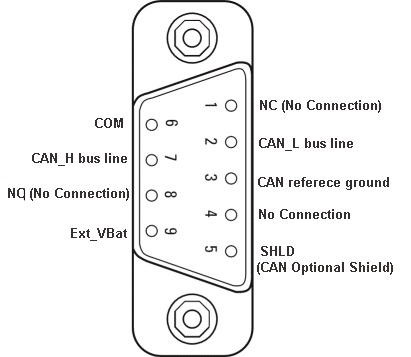
DB9 Pinout
Boot Key Recovery
When working in the prototype phase with newly created *.srz files from MotoHawk, it is possible to program an *.srz with errors in the CAN software or in the model that prevent communications with the module once programmed. When this happens, the module appears to be locked up or frozen when accessing the module via MotoTune. In this case, use the boot key to force the module into reboot mode such that a known, valid *.srz can be reprogrammed into the module.
Understanding Boot Key Functionality
The boot key has a 10-pin CAN connector that should be inserted into an open port on the CAN junction box. The device generates a 555 Hz, 5V signal out of pin E when power is applied to pin A and ground applied to pin B.
At power-on, the hardboot loader for the module first looks to see if the boot key input or boot cable sequence is present. If so, the code prepares to accept programming. If no programming instructions are received from MotoTune within a few seconds (~3), then the existing program application is started, and recovery is not successful. At power-on (BATT and KEY_SW), if the hardboot loader does not detect the boot key signal (or boot harness sequence), then the hardboot loader skips the three-second wait and starts the existing application. So, the ECU must see the boot key signal immediately when it powers up.
Note: It can help, especially on the 112-pin modules, to energize the boot key before the module (you may need to disconnect the connector between ECU and the junction box but leave power to junction box).
The recovery procedure is as follows:
1. Plug the boot key into the junction box and make sure that power and ground are connected to pins A and B on the junction box. Connect pin E of the junction box to the channel listed below on the following modules.
- ECM-555-48 – ESTOP
- ECM-555-80 – ESTOP
- PCM-565-128 – DG1
- HCM-563-48 – STOP
- GCM-563-48 – STOP
- If the boot key fails to work with the above two GCM/HCM 563-48 modules, refer to Fire48 Hardboot Recovery. In order to purchase a boot cable, visit HARN-ECM-022
- When using the boot key with the GCM/HCM48, power must be applied to the boot key before power is applied to the module, because the boot up procedure on those modules is so quick that, otherwise, the boot procedure will be over before the boot key can send the signal. We've found the boot harness to be a more reliable way to boot those modules.
- ECM-5554-112 – STOP
- HCS-12 (GCM 24-pin modules) - Refer to HCS12 Boot Connections for GCM 24-Pin Module
- SECM24
- Tie pins 1, 4 and 15 together
- Tie pins 3, 5, 17 and 18 together (and pin 16 on the SECM24-0804)
- Tie pin 13 to battery power
- Tie pin 14 to battery ground
- Tie pin 6 to CAN+ and pin 19 to CAN-
- ECM-OH main core - DG8
- Note: The ECM-OH is programmed at the factory with a sample application that sets CAN-1 of both the Main and Auxiliary Cores to 500K baud rate. Both cores are internally connected within the ECU on CAN-1. If the baud rate of one of the cores is changed on CAN-1, then the baud rate of the other core must be programmed to match CAN-1.
- For programming the ECM-OH, it may help to think of it as two modules connected on CAN-1: the main and the aux S12G. Since the cores are internally connected on CAN-1, the baud rate must be the same for both on CAN-1, and they must have different city IDs. The module ships pre-programmed with an application that sets the baud rate for both cores to 500K, with the city ID of main as 0xB and the city ID of the aux as 0x81.
- The hardboot (the settings used to program the module by boot key or boot harness) if it needs to be recovered is:
Main:
250K b/s
City ID 0xB
Aux:
250K b/s
City ID 0x81 - To change the baud rate on CAN-1, first program the main core. Cycle power to put auxiliary in hardboot, then program the auxiliary as above.
- ECM-563-48 – Does not use a boot key.
- There are two approaches to recovering the module:
- Use a Boot Cable (p/n HARN-ECM-013), purchased at HARN-ECM-013. Download the drawing from Harness Documentation.
- To boot strap the ECM-563-48 modules, connect the following channels and follow the steps below.
AN1 – AN6 Pull to +5V
AN8 Pull to GND
AN11 - AN12 Pull to +5V
- There are two approaches to recovering the module:
- ECM-S12X-70-1001 - Does not use a boot key.
- There are two approaches to recovering the module:
- Use the Programming Harness (p/n HARN-ECM-029), purchased at HARN-ECM-029.
- In addition to battery power, ground, key-switch and CAN+/-, connect the following channels before programming:
Tie AN02, AN03 and AN07 to XDRGND1
Tie AN01, AN04, AN05 and AN06 to XDRPWR1
Battery power to DRVP1
- There are two approaches to recovering the module:
2. With the power to the module off and the boot key installed, select a known, valid *.srz file to flash onto the module and program the module at 250kbps on the module's default city ID. All modules default to city ID PCM-1 (0x0B) with the following exceptions:
- ECM-S12 - SECM-1 (0x81) (Not applicable to ECM-S12-24-0804, which defaults to PCM-1)
- GCM-S12 - uCHI-1 (0x91)
3. When the “Looking for an ECU” prompt appears in the dialogue box, turn on power to the ECU. The module must “wake-up” with the boot key applied in order to force a reboot.
Voltage Specifications for Modules
While all the modules are designed to withstand momentary short-to-battery on the input sensor pins (except those that inherently cannot be protected), the hardware validation test is typically one minute short-to-battery.
In the case of analog and digital inputs (nominal 5V), the circuit may not be able to dissipate heat when connected to a higher voltage on a longer timeframe. For instance, the pull-up or pull-down resistor may not be sized to dissipate heat from that higher voltage (resistor wattage rating).
+++++
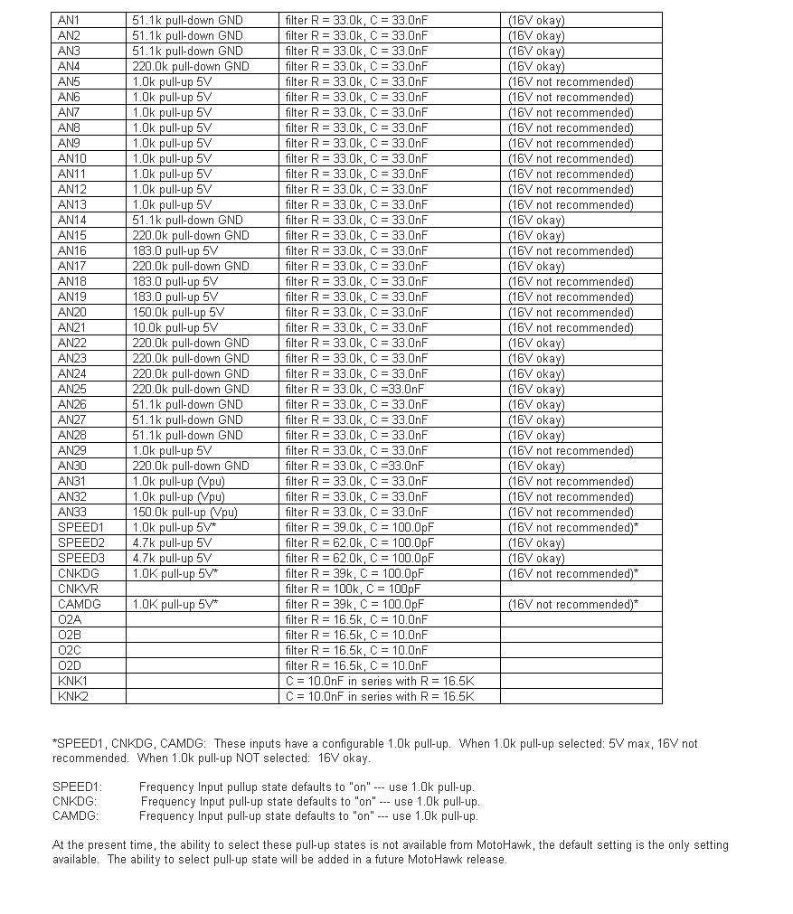
For the circuits marked "16V okay" in the table below, the resistor wattage rating is such that continuous operation at 16V should be okay.
"Double Battery" situation: At nominal 24V (as high as 32V jumpstart), the trace widths as well as the PU/PD resistor may be vulnerable. Some of the pull-downs would likely be okay, but this should be verified. For example, AN4: 220kΩ pull-down ---> P = (V^2) / R = (32*32) / (220e3) = 0.005 W = 5 mW. The resistor for AN4 is rated 63 mW. Depending on ambient temperature for the module (heat transfer from the resistor, module body type, ambient temperature), this circuit may be okay for short "double battery" exposure.
H-Bridge Wiring
The H-bridge is normally wired as:
(H+)----(load)----(H-)
and the H-bridge circuit is powered from DRVP internally.
(BATT)----(MPR Common, MPR Normally Open)----(DRVP)----(to H-bridge and other internal devices and flyback diodes).
The low side of the H-bridge circuitry connects to DRVGx and then back to battery ground.
In one H-bridge, the fault/current feedback line is shared between each half bridge. Therefore, you can only get reliable fault or current data when using it as an H-bridge or using one half bridge only. If both half-bridges are used independently, the fault/current feedback line will provide unreliable data for either of them.
CAN Addressing Conflicts
You may run into issues with MotoTune's CAN messaging conflicting with other CAN communications in your system. It is possible to change the CAN IDs on which MotoTune communicates to avoid this. This section will describe how to do so.
You will need to make changes to both your model and your MotoTune configuration to support the new MotoTune communication CAN IDs.
Model Configuration
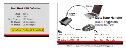
- Disable the MotoTune Protocol in the CAN Definition block
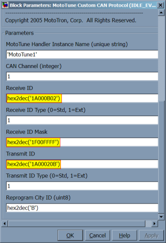
- Add the MotoTune Custom CAN Protocol Handler block (Idle Triggered)
- RX ID = hex2dec('1A000B02')
- RX ID mask = hex2dec('1F00FFFF')
- TX ID = hex2dec('1A00020B')
-
MotoTune Protocol Disabled
-
New CAN IDs for the MotoTune Custom CAN Protocol block
MotoTune/MotoServer Configuration
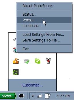
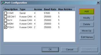
- Open MotoTune and configure the MotoServer Ports
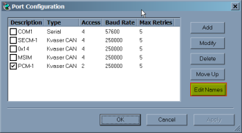
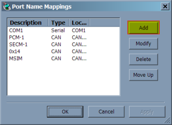
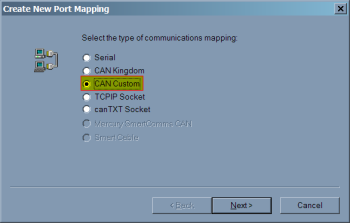
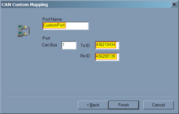
- Edit Port Names and create a Custom CAN Mapping
- TX ID: 436210434 (this is 0x1A000B02, but use decimal here)
- RX ID: 436208139 (this is 0x1A00020B, but use decimal here)
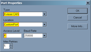
- Create a new Port configuration
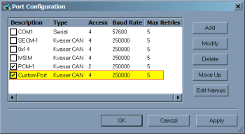
- After flashing the module, the MotoTune protocol will no longer be available on PCM-1 and will only be available on the new custom mapping.
-
MotoTune context menu
-
Edit Names
-
Add a port name
-
Select 'CAN Custom'
-
Enter your name and the appropriate CAN IDs
-
Add a port configuration
-
-
Now your custom port is in the ports list!
-
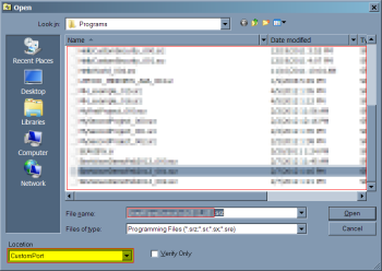
Don't forget to select it in the Program dialog box
MotoTune dongle is plugged in, but MotoViewer won't open.
In order to open up Motoviewer, a separate MotoService dongle is required.
MotoTune has stopped working after a Re-install/Update.
- If you are upgrading from 8.13 to 10.0, please uninstall 8.13 first then install 10.0 if you have encountered issues.
- When downgrading from 10.0 to 8.13, please uninstall 10.0 and the MotoLicense Handler before installing the 8.13 version of MotoTune
Implementing J1587 Protocol on a J1708 Hardware Layer (using a MotoTron RS485 Driver)
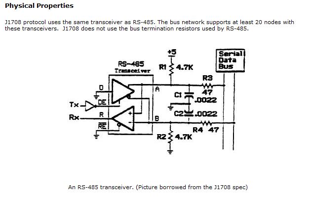
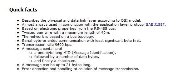
An RS485 software driver in MotoHawk can be written for J1587. The hardware signal conditioning and some general J1587 notes follow:
Communication Between Serial Port on ECU and USB Device Over RS485
Let's assume you want to use the USB with a laptop/PC and enable Mototune to communicate over RS485. So, when the hardware is connected to the PC, it would be recognized by the computer, say as COM7 port.
- Add a New Port by going to Motoserver -> Ports -> Add. In the window that appears, select ‘Serial’ under Type and ‘COM7’ under Location.
- ‘Serial I/O Blocks’ in the MotoHawk blockset will help define the communication over a specific protocol, RS485 in this case.
Hall Effect Inputs
Variable Reluctance Inputs
DC Motor Drive
Can a MotoHawk module drive a DC Motor? If current is going one way, you can use a low-side drive. You can parallel LSDs to get the power required. For example, a 12V, 150-watt motor would require 12.5 amps of drive.
S12(X) Recommended Stack Size
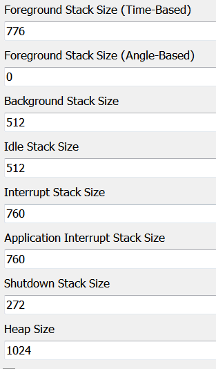
The "Working with the S12" Application Document indicates a stack baseline when starting your application. Below is another recommended stack size if the stack baseline is low in certain areas. This is applicable towards the 24-pin and 70-pin controllers that use the Freescale S12 or S12X processors.
Note: The following stack sizes are recommendations and should be adjusted according to the application requirements.
Grounding the ECU cases
All MotoHawk ECU cases should be mounted through non-conductive vibration isolators and are NOT intended to be externally grounded. They function as an EMI shield and are RC coupled to the PCB ground plane. Grounding the case will not impact the functionality of the unit but may affect the EMC performance and ESD protection.
