Analog I/O Blocks: Difference between revisions
No edit summary |
No edit summary |
||
| Line 35: | Line 35: | ||
This MotoHawk™ block is configurable for controlling pulse-width modulation (PWM) output specifically for HBridges. | This MotoHawk™ block is configurable for controlling pulse-width modulation (PWM) output specifically for HBridges. | ||
Block ID | |||
HBridge_Output | HBridge_Output | ||
Library | |||
MotoHawk_lib/Analog I/O Blocks | MotoHawk_lib/Analog I/O Blocks | ||
Description | |||
[[Image:hbridge_output.png]] | [[Image:hbridge_output.png]] | ||
| Line 49: | Line 49: | ||
This block includes the Frequency and Duty Cycle (DC) inputs, DC values range int16 -4096 to 4096, where 0 represents 0% and 4096 is 100%. Positive values have the current flow from H(A/+) to H(B/-) negative values will have current flow from H(B/-) to H(A/+). The Frequency input is uint32 which represents 0.01Hz. This block differs from the [PWMOutput.html PWM] block in that it holds both legs low and PWMs one leg high for current flow. The PWM block will hold both legs high and PWM one of the legs low. The percent braking PWMs both legs low for the duty cycle and will float rest of the time. | This block includes the Frequency and Duty Cycle (DC) inputs, DC values range int16 -4096 to 4096, where 0 represents 0% and 4096 is 100%. Positive values have the current flow from H(A/+) to H(B/-) negative values will have current flow from H(B/-) to H(A/+). The Frequency input is uint32 which represents 0.01Hz. This block differs from the [PWMOutput.html PWM] block in that it holds both legs low and PWMs one leg high for current flow. The PWM block will hold both legs high and PWM one of the legs low. The percent braking PWMs both legs low for the duty cycle and will float rest of the time. | ||
Block Parameters | |||
{| class="TableMHStyle" | {| class="TableMHStyle" | ||
Revision as of 16:24, 5 February 2014
A
MotoHawk:Blocks:Analog Input
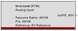
This MotoHawk® block outputs a uint16 value from 0 to 1023, representing 0 to 5V, sampled at the A/D converter. Select a unique resource name. This name can be the name of the sensor that is being read. If none is given, it will either inherit the pin name or the vardec name, depending on whether calibrateable IO is selected.
Choose the pin resource to read. For some modules, a lower reference voltage is available for each ADC channel.
"Output Creation Status" will add an optional uint16 output that provides the ControlCore error status. 0 means OK, and any other number is an error. Please type 'help motohawk_enum_error' for more information. This can be useful for disabling diagnostics or strategies based on different I/O calibrations.
MotoHawk:Blocks:Analog Input Reference
This MotoHawk® block outputs a uint16 value from 0 to 1023, representing 0 to 5V, sampled at the A/D converter. Choose the resource name (specified in the Analog Input block) to specify the analog input channel to reference. Either choose the resource to reference, or provide the name of a resource by name.
MotoHawk:Blocks:Analog Output
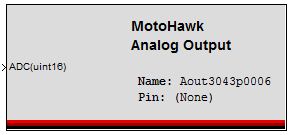
The MotoHawk® Analog Output block is used to control an internal resource on the GCM-5554-112-1001 (CCM1001) module, target '1751-6456 1751-6457' in the MotoHawk target definition block. It is not used for any external output pin. At present, it only supports the internal VISTA_DAC2 resource on this one module [MotoHawk 2009a and later; 21-Jan-2010].
Other options for generating an analog voltage output are discussed here:
This MotoHawk® block drives an analog output based on a uint16 value from 0 to 65535, representing negative rail voltage to positive rail voltage. Select a unique resource name. This name can be the name of the sensor that is being read. If none is given, it will inherit the pin name. Choose the pin resource to read.
H
HBridge Output
This MotoHawk™ block is configurable for controlling pulse-width modulation (PWM) output specifically for HBridges.
Block ID
HBridge_Output
Library
MotoHawk_lib/Analog I/O Blocks
Description
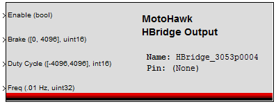
This block includes the Frequency and Duty Cycle (DC) inputs, DC values range int16 -4096 to 4096, where 0 represents 0% and 4096 is 100%. Positive values have the current flow from H(A/+) to H(B/-) negative values will have current flow from H(B/-) to H(A/+). The Frequency input is uint32 which represents 0.01Hz. This block differs from the [PWMOutput.html PWM] block in that it holds both legs low and PWMs one leg high for current flow. The PWM block will hold both legs high and PWM one of the legs low. The percent braking PWMs both legs low for the duty cycle and will float rest of the time.
Block Parameters
| Parameter Field | Values | Comments/Description |
| Name | Alpha-numeric text, single-quote enclosed | Name as displayed in MotoTune, for block. No special characters, such as spaces, dashes, commas (underscore allowed) |
| Resource | Drop-down list | Select from available resource, per target ECU, such as H-bridge, etc. |
| Input Enable | Check box (enable) | When "Input Enable" is checked, the output may be dynamically controlled. When disabled, the output transistors are completely turned off, which will stop all current, but also disable any diagnostics. |
| Input Brake | Drop-down list | Select "Off/On" to have a boolean switch for braking, or select "Percent" to PWM the brake at the duty cycle specified at the Brake input. A non-zero value on the Brake input overrides the Duty Cycle input. Note: When using Brake in Percent mode, no faults will be reported. |
| Use Minimum Frequency | Check box (enable) | Enables the Minimum Frequency (Hz) field. |
| Minimum Frequency (Hz) | Numeric | Setting this value tunes the clocks used for PWM generation and should be set to the minimum expected frequency. The Frequency input is uint32 and each unit represents 0.01Hz. |
| Use Maximum Frequency | Check box (enable) | Enables the Maximum Frequency (Hz) field. |
| Maximum Frequency (Hz) | Numeric | Setting this value tunes the clocks used for PWM generation and should be set to the maximum expected frequency. The Frequency input is uint32 and each unit represents 0.01Hz. |
P
MotoHawk:Blocks:Synchronized PWM Child
This MotoHawk® block, a synchronized PWM child, references a PWM Output parent block, and drives the output with a square wave with a specified phase offset relative to the parent. The child may have an independent duty cycle. Either choose the resource to reference, or provide the name of a resource by name, as defined by a PWM Output block. This is necessary when the parent pin is made calibratable.
The Duty Cycle input is an int16, ranging from -4096 to 4096, where 0 is 0%, 4096 is 100%. When negative, the polarity is reversed, which is only valid on PWM resources that are H-Bridge outputs, like ETC or H1. When "Output Current" is checked, the drive current in milliamps is provided. When "Output Fault Status" is checked, a value indicating fault status is provided. This value is one of: 0 - OK 1 - Fault 2 - Indeterminate
The Synchronized PWM Child block only works with 5xx processor targets, each parent can only have two or fewer child PWMs, and the parent and child resources must reside on the same TPU bank. For more information on the PWM child block, for example which outputs are on which TPU bank, select the help button on the block.
MotoHawk:Blocks:PWM Output
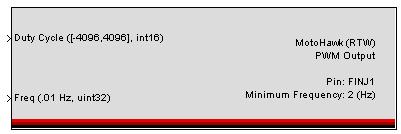
This MotoHawk® block's Duty Cycle input is an int16, ranging from -4096 to 4096, where 0 is 0%, 4096 is 100%. When negative, the polarity is reversed, which is only valid on PWM resources that are H-bridge outputs, like ETC or H1. The Frequency input is a uint32, ranging from 119 to 19988175. Each unit represents 0.01Hz. The actual range is limited.
When "Input Enable" is checked, the output may be dynamically controlled. When disabled, the output transistors are completely turned off, which will stop all current, but also disable any diagnostics. When "Output Current" is checked, the drive current in milliamps is provided. When "Output Fault Status" is checked, a value indicating fault status is provided. This value is one of: 0 - OK 1 - Fault 2 - Indeterminate When "Use as parent for synchronized PWM" is checked, a Synchronized PWM Child block may be used to reference this block.
MotoHawk:Blocks:PWM Peak and Hold Output
W
MotoHawk:Blocks:Wide Range O2 Sensor
Choose the pin resource to read. Note, this block is only available on the ECU565-128 target.
