Controllers: Difference between revisions
| Line 43: | Line 43: | ||
[[Image:Module_Family_Overview.JPG]] | [[Image:Module_Family_Overview.JPG]] | ||
=== | ===ECM Summary=== | ||
Coming soon | |||
=Controllers= | =Controllers= | ||
Revision as of 19:57, 29 July 2010
Introduction to New Eagle Controllers
New Eagle Control Module Naming Scheme
The New Eagle naming scheme is broken into four main parts: type of control module, type of microprocessor, number of pins, and model year & variant. An extra sequence of numbers/letters may be seen at the end which determine certain model features such as flash, calibratible, or mounting feet.
What does this mean?
ECM-565-128-0701-C
- Start by looking at the first section which determines the type of control model. The model in the above example is an ECM (Engine Control Module) as opposed to a GCM (General Control Module), HCM (Hydraulic Control Module), EVM (Electric Vehicle Module), or VCM (Vehicle Control Module)
- The second part describes the type of microprocessor the module has. The above module has a MPC565 Microprocessor.
- The third part shows the number of pins that the module has. The example module has 128 pins.
- The fourth section consists of the model year and the model variant. In the above example, the control model has a model year of 2007 and is the first variant.
- The next section that may appear when naming modules determines certain features that the model may have. 'C' stands for Calibratible - thus the above module is calibratible. Other Endings may include 'F' (Flash), 'M' (Mounting Feet), 'CPO' (Calibratible "DEV" Development Module), and 'F00' (Flash "PROD" Production Module).
- The last letter is M or it is blank. M means mounting feet are included.
Module Naming Quick Cheat Sheet:
Module: ECM-555-80-xxyy-CP0/F00-M
ECM = engine control module
555 = MPC 555 microprocessor
80= 80 pins
xx = model year (e.g. 07 = 2007 model year)
yy = variant of 80-pin model for xx model year (e.g. 03 = third variant).
-CP0 = calibratable "DEV" development module
-F00 = flash "PROD" production module
The next two letters are important for modules in development, not to be confused with a development module. The letters change as they develop or move from concept to release. The letters are F00 meaning production.
The final letter is M meaning rubber mounting feet attached. If the part number does not end in a M, the module will not come with feet.
New Eagle Module Part Overview
File:Module Family Overview.JPG
ECM Summary
Coming soon
Controllers
Engine Control Modules (ECM)
Engine control modules (ECM) differ from the general and hydraulic in that some inputs and outputs are customized for engine performance.
ECMs custom outputs for:
- Fuel Injection
- Spark Timing
ECM custom inputs for:
- Oxygen Sensors
- Knock Sensors
Signal Conditioning Includes:
- Inputs:
- Numerous Analog Inputs
- VR/Hall Frequency Inputs
- Outputs:
- Low Side Injector Drivers
- TTL Level Ignition System Outputs
- High Current Low Side PWM
- 5A H-Bridge PWM with Current Feedback
- Independent Transducer Power Supply
- Low Side Relay Driver (Main Power)
- Datalinks:
- CAN 2.0B Channel
Module families:
- ECM-555-48
- ECM-555-80
- ECM-563-48
- ECM-565-128
- ECM-S12-24
- ECM-5553-112
- ECM-5554-112
- ECM-XC2-24
Learn More About MotoHawk Engine Control Modules
General Control Modules (GCM)
Inputs and outputs for the General Purpose line of controllers include:
- Inputs:
- 11 to 18 Analog
- 2 to 8 Discrete/Frequency
- 0 to 2 Hall Effect Frequency (cam)
- 0 or 2 Variable Reluctance Frequency (crank)
- 1 Stop
- Outputs:
- 6 Low Side Driver
- 2 High Side Driver
- 1 H-Bridge Driver (10A)
- 1 Digital
- 1 Main Power Relay Driver
- Datalinks:
- Up to 3 CAN 2.0B Channels
Model families:
- GCM-563-48
- GCM-565-24
- GCM-S12-24
- GCM-S12-XX
- GCM-S12-36
Hydraulic Control Modules (HCM)
Inputs and outputs for the Hydraulic line of controllers include:
- Inputs:
- Up to 16 Analog
- Up to 6 Discrete/Frequency
- Up to 2 VR/Hall Frequency
- 1 Knock/Drive Noise Detector
- 1 Stop
- Outputs:
- 6 2.5A Low Side Drivers w/Current Feedback
- 4 3A Low Side Drivers
- 1 1A EasyLink/Low Side Driver
- 1 Relay Driver (Main Power)
- Datalinks:
- 2 CAN 2.0B Channels
- Module families:
- HCM-563-48
Electric Vehicle Modules (EVM)
VIM-5567-24
The VIM-5517-24 Integration Controller family consists of a rugged automotive grade controller capable of multiple CAN protocols and serves as a stand-alone controller or as an I/O expansion to the existing line of MotoHawk ECUs. Multiple CAN hardware choices allow this module to act as a CAN "Gateway" to systems requiring differing communications protocols. This module also provides interface with inputs, outputs and communication protocols that support a wide variety of applications and adds additional layers of capability to existing MotoHawk ECUs when used as an enhancement module. A customizable circuit board allows for unique signal conditioning to meet your needs.
- Hardware Features:
- Freescale MPC5517 Microprocessor
- Operating Voltage: 8-32 VDC
- Operating temperature ranging from -40°C to 105°C
- Sleep mode current draw: < 1mA
- Custom signal conditioning circuit board
- Software Features:
- "Wake Up on CAN" Capability
- "Wake on Charge" Interface (J1772)
- "Sleep Mode" Capability"
- "Watchdog" Capability
- CAN Gateway
Vehicle Power Interface Module
The Vehicle Power Interface Module (VPIM) provides the necessary circuitry to interface with Electric or plug-in Hybrid Electric vehicle charging equipment in accordance with the SAE J1772 specifications. It allows the vehicle systems and ECUs that require a low current "sleep" mode to be managed externally and monitors the inputs, providing an output that will drive an external "Wake Up" relay which, in turn, provides power to the connected systems.
Features include:
- Operating Voltage: 8-30 VDC
- J1772 Hardware Interface
- Low Current Consumption < 10mA
- Operating Temperatures ranging from -40°C to 105°C
Vehicle Control Modules (VCM)
MotoHawk Line of Controllers and Specifications
Please visit the following MotoHawk ECU Summary Page for MotoHawk controller family availability. This is a good starting point to help select a family for which numerous part numbers can be found by searching the data sheets in the download section (login required, can be requested by sales at neweagle.net).
Controllers in development are also found in the download section of our site.
RoHS and MotoTron ECU Modules
Motorola had been pushing for RoHS compliance across the company since they are mainly consumer products, but when Conti took over there is no longer this push. There is no plan to go lead-free on solder for Visteon or Conti. The impact to the part design (higher reflow temps) and manufacturing is too great.
Controller Quality Certification
Both Visteon and Continental built MotoHawk modules (24, 48, 80, 128 pin modules) have QS-9000/TS16949 quality certification.
MPC5XX EEprom Clarification
- All XXX-563-48 controllers have 16k of EE. - The ECM555-80 and ECM555-48-0710 have 8k - All other ECM555 have 4k.
Future MotoHawk Controllers
The MotoHawk (MotoTron) family of controllers is growing and expanding. New functions and replacement plans can be found in the download section (enter link A.).
General Comments
Voltage Specifications for Modules
While all the modules are designed to withstand momentary short-to-battery on the input sensor pins (except those that inherently cannot be protected), the hardware validation test is typically 1 minute short-to-battery.
In the case of analog and digital inputs (nominal 5-volt), the circuit may not be able to dissipate heat when connected to a higher voltage on a longer timeframe. For instance, the pull-up or pull-down resistor may not be sized to dissipate heat from that higher voltage (resistor wattage rating).
+++++
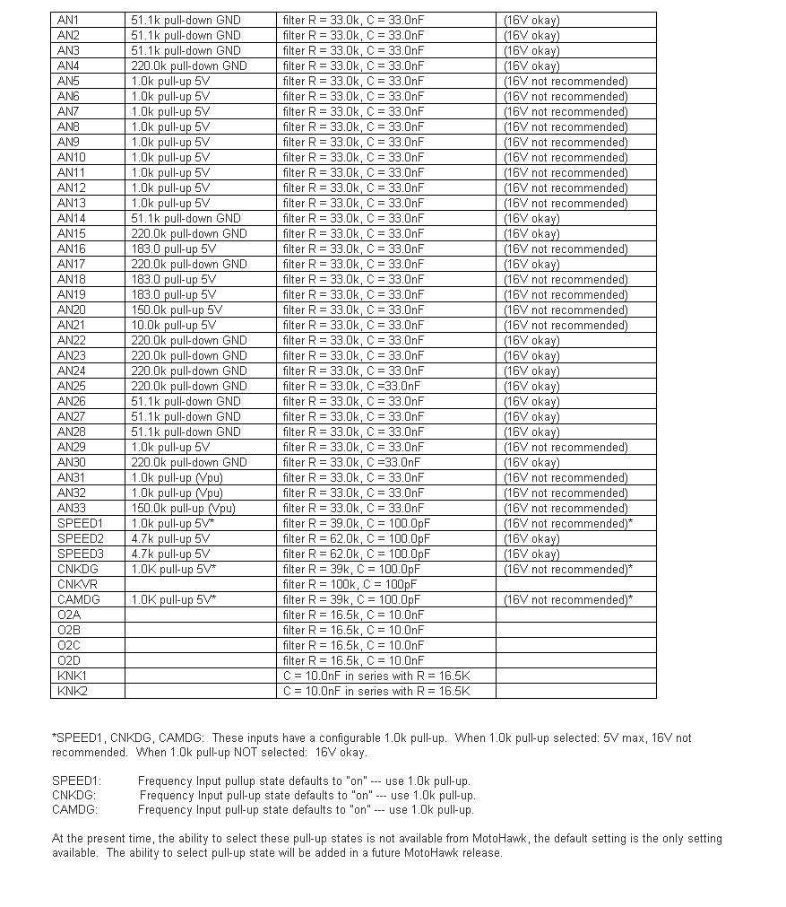
For the circuits marked "16V okay" in the table below, the resistor wattage rating is such that continuous operation at 16V should be okay.
"Double Battery" situation: If there is a particular circuit, let me know and we can check. At nominal 24V (as high as 32V jumpstart), the trace widths as well as the PU/PD resistor may be vulnerable. Some of the pull-downs would likely be okay, but this should be verified. For example, AN4: 220k-ohm pull-down ---> P = V2 / R = 32*32 / 220e3 = 0.005 W = 5 mW. The resistor for AN4 is rated 63 mW. Depending on ambient temperature for module (heat transfer from resistor, to module body, to ambient), this circuit may be okay for short "double battery" exposure.

H-bridge Wiring
The H-bridge is normally wired as: (H+)----(load)----(H–) and the H-bridge circuit is powered from DRVP internally. (BATT)----(MPR Common, MPR Normally Open)----(DRVP)----(to H-bridge and other internal devices, and flyback diodes). The low side of the H-bridge circuitry connects to DRVGx and then back to battery ground.
ECM Differences
| MotoHawk Target | Current MotoTron part numbers (What to ask for When Ordering) | |
| ECM-0555-048-0706 | EC-0555-048-0701 (-0706 not produced, replaces -none-) | <--VR crank |
| ECM-0555-048-0707 | ECM-0555-048-0707 (-0702 no produced, Replaces -0402) | <--VR crank |
| ECM-0555-048-0708 | ECM-0555-048-0708 (-0703 not produced, replaces 0401) | <--Diital/Hall crank |
| ECM-0555-048-0709 | ECM-0555-048-0704 (0809 not produced, replaces -0401) | <--VR crank |
| ECM-0555-048-0710, ECM-0555-048-0403 |
ECM-0555-048-0710 (-0705 not produced, replaces -0403) | <--VR crank (either MH target should work) |
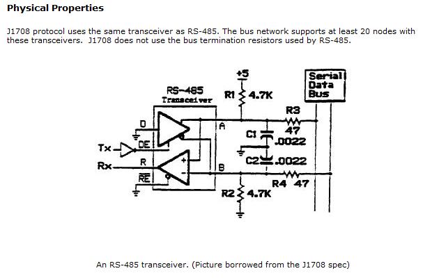
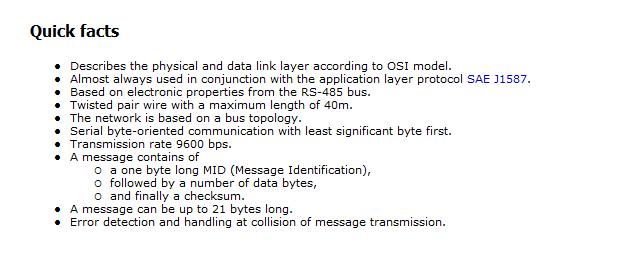
Implementing J1587 Protocol on a J1708 hardware layer (using a MotoTron RS485 Driver)
A RS485 software driver in MotoHawk can be written for J1587. The hardware signal conditioning and some general J1587 notes follow:

