More Information GCM-S12-24: Difference between revisions
No edit summary |
|||
| Line 63: | Line 63: | ||
=Webstore= | =Webstore= | ||
'''[http://store.neweagle.net/products-by-category/controllers-1/general-control-modules.html Webstore: General Control Modules]''' | '''[http://store.neweagle.net/products-by-category/controllers-1/general-control-modules.html Webstore: General Control Modules]''' | ||
=Other Modules= | |||
'''[[Controllers | Back to: Controllers]]''' | |||
Revision as of 19:12, 5 December 2016
GCM-S12-24
Product Summary

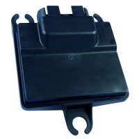
This module is capable of operating in harsh automotive, marine, and off-highway applications. The CAN 2.0B datalink ensures interoperability with other system components.
- Features include:
- Freescale MC9S12DT128, 24 MHz Microprocessor
- Operating Voltage: 8-16 VDC
- Operating temperatures ranging from -40°C to 105°C
- Sealed connectors operable to 10 ft. submerged
Datasheets
GCM-S12-24 FAQs
- If you change the city ID and/or baud rate you need to cycle power for the new settings to take place.
- There is no main power relay on this ECU, but there is a key-switch. This means sleep mode works differently for this module. The software needs to turn the module into sleep mode, normally the Main Power Relay block would do this, but that block does not work for the GCM-S12-24 since there is no MPRD pin. Thus, you need to create your own code to manage sleep mode of the block. The model will still compiler with the MPR block, but the block will not do anything.
- All modules from the GCM-S12-24 family use the same target in MotoHawk. When programing the 0402 and 0403 modules in MotoTune, you will get an error message, due to a compatibility check MotoTune performs before programming. In this case chose the program anyways response since all modules from the GCM-S12-24 family are the same with the exception of their pull up/pull down values.
- pull up pull down values
- GCM-0S12-024-0401-F00 (MCHI0401)
- AN1 -- 220.k PD
- AN2 -- 220.k PD
- AN3 -- 220.k PD
- AN4 -- 220.k PD
- AN5 -- 220.k PD
- AN6 -- 220.k PD
- GCM-0S12-024-0402-F00 (MSIM0401)
- AN1 -- 51.1k PU
- AN2 -- 1.00k PU
- AN3 -- 180. PU
- AN4 -- 220.k PD
- AN5 -- 180. PU
- AN6 -- 1.00k PU
- GCM-0S12-024-0403-F00 (SMUX0401)
- AN1 -- 1.00k PU
- AN2 -- 1.00k PU
- AN3 -- 1.00k PU
- AN4 -- 1.00k PU
- AN5 -- 1.00k PU
- AN6 -- 1.00k PU
Current Draw on the 24-Pin Family
Power draw should be the base below, plus power required for sensor inputs (from XDRP) and driven loads.
- SECM08xx(ECM PROD): approx. 100mA at 13.8V (key on, module-only, no external loads or sensors).
- SECM08xx (ECM DEV) : approx. 270mA at 13.8V (key on, module-only, no external loads or sensors).
- MCHI04xx (GCM PROD): approx. 100mA at 13.8V (key on, module-only, no external loads or sensors).
- MCHI04xx (GCM DEV) : Does not exist.
The above numbers are from a quick test here on-bench for the various modules, with a baseline "empty" application and with nothing but power, ground and CAN connections. The SECM08xx (ECM DEV) draws additional current to drive the additional calibratable memory circuitry. This data comes from one SECM 24-pin DEV module.
For the MCHI04xx (GCM) family, the key-off fully-shutdown power draw on BATT should be less than 0.5mA.
Difference Between ECM0502 and GCM0402
When the controllers shut down, there is a difference in the way calibrations are stored. ECM does not have separate key-switch and battery pins so there is no way the controller would know to save the calibrations before a shutdown. In this case, it would have to save these values periodically; whereas, in the case of a GCM, there are two separate key-switch and battery pins so the module can save Non-Volatile data when a shutdown is commanded and then go to sleep.
- Family includes:
- GCM-S12-24-0401
- GCM-S12-24-0402
- GCM-S12-24-0403
Working with the S12 MotoHawk Application Document
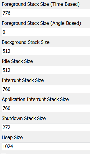
The "Working with the S12" Application Document indicates a stack baseline when starting your application. Below is another recommended stack size if the stack baseline is low in certain areas.
NOTE: The following stack sizes are recommendations and should be adjusted according to the application requirements.
Non-Volatile Memory Note
GCM24-0401 module also has a battery input, which means it can do the saving to EEPROM during a controlled shutdown (many of the other 24 pin modules don’t have a battery input, which means a controlled shutdown is not possible and thus nonvolatile variables need to instead be stored periodically during run-time).
Webstore
Webstore: General Control Modules
