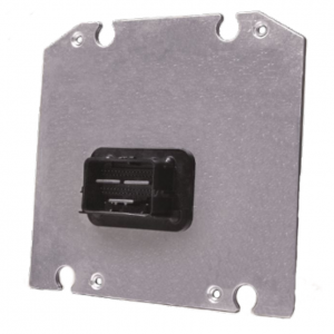
GCM-5634M-70-1459: Difference between revisions
(→FAQ) |
|||
| Line 34: | Line 34: | ||
'''Power Cycle Instructions:''' | '''Power Cycle Instructions:''' | ||
*Step 1: Remove all power to the module. Make Sure Key switch is off. | *Step 1: Remove all power to the module. Make Sure Key switch is off, with the Boot Key connected to the bus. | ||
*Step 2: From Raptor-CAL/Service: Select Program, then the recover check box, MotoHawk, Select the .RPG file. | *Step 2: From Raptor-CAL/Service: Select Program, then the recover check box, MotoHawk, Select the .RPG file. | ||
*Step 3: Click OK, turn on power supply, then key switch. | *Step 3: Click OK, turn on power supply, then key switch. | ||
Revision as of 19:43, 16 January 2018
GCM-5634M-70-1459
The ECM-5634M-70-1459 is a general purpose control module. The module has 2 CAN buses, and sports a 3-phase motor driver. The eclectic inputs and outputs make this module suitable for a wide variety of general purpose applications.
The ECM-5634M-70-1459 is part of a family of rugged, automotive-grade production controllers that use a software development process based on MATLAB/Simulink, known as Raptor-Dev. Raptor-Dev significantly speeds up algorithm development by using automatic code generation. In addition, developers can quickly test application software on their PCs with a built-in onscreen PC simulation.
Data Sheet
- GCM-5634M-70-1459
Pins and Crimping
Need to make a harness? Click here to get started.
Want to buy a pre-made harness? Click here to order.
Compiler
GCC PowerPC EABI 4.6.0
FAQ
SPD1 Limit
The frequency speed limit in the SPD1 resource is designed for 10K.
Recovery Procedure (Boot Key)
The GCM70 requires a Boot Key to recover the module. These can be found on our store page
The use the boot key to recover the malfunctioned module, please follow the Raptor-Cal MotoHawk Module Recovery steps provided: Boot Key Recovery and below.
Note: The Boot Key signal (Pin E on the Smartcraft connector) needs to be connected to the SWG4 pin for the GCM70.
Power Cycle Instructions:
- Step 1: Remove all power to the module. Make Sure Key switch is off, with the Boot Key connected to the bus.
- Step 2: From Raptor-CAL/Service: Select Program, then the recover check box, MotoHawk, Select the .RPG file.
- Step 3: Click OK, turn on power supply, then key switch.
