ECM-565-128: Difference between revisions
| Line 31: | Line 31: | ||
*Obsolete FET was changed | *Obsolete FET was changed | ||
*There are no software implications to using the 0707 over the 0702 | *There are no software implications to using the 0707 over the 0702 | ||
ECM-065-128-0702-CP0 is a minor revision of ECM-0565-128-0701-CP0. The same datasheet applies to both. | |||
===Technical Manuals=== | ===Technical Manuals=== | ||
| Line 39: | Line 42: | ||
'''ECM-0565-128-0701-F | '''ECM-0565-128-0701-F | ||
:'''[https://www.woodward.com/-/media/publication-assets/technical-manual/2019/4/18/18/40/36321.pdf Technical Manual] | :'''[https://www.woodward.com/-/media/publication-assets/technical-manual/2019/4/18/18/40/36321.pdf Technical Manual] | ||
===Datasheet Errata=== | ===Datasheet Errata=== | ||
There are a few | There are a few errors in the datasheets. '''To clarify: | ||
ECM-0565-128-L701-Fxx, flash (no calibratable memory) "PROD" production module. | ECM-0565-128-L701-Fxx, flash (no calibratable memory) "PROD" production module. | ||
| Line 59: | Line 59: | ||
The PCM128 modules are nearly identical. The "PROD" -F module has four (4) extra analog inputs and four (4) extra digital inputs; the "DEV" -C module has two (2) wide-band oxygen (lambda) sensor inputs and two (2) extra knock channels, as well as additional RAM. For the 2007 model-year, these modules have three H-bridges: 10-amp continuous, 12-amp peak. (The datasheet is being updated to reflect the higher ampacity capability of H1 and H2, due to board layout revision.) | The PCM128 modules are nearly identical. The "PROD" -F module has four (4) extra analog inputs and four (4) extra digital inputs; the "DEV" -C module has two (2) wide-band oxygen (lambda) sensor inputs and two (2) extra knock channels, as well as additional RAM. For the 2007 model-year, these modules have three H-bridges: 10-amp continuous, 12-amp peak. (The datasheet is being updated to reflect the higher ampacity capability of H1 and H2, due to board layout revision.) | ||
===Supplementary Details=== | |||
The low-side fuel injector drivers INJx may be run as 3A peak/1A hold (all 12 injector drivers), or 7A peak/3A hold (6 drivers as indicated). Use the "Injector Current Select" block in the MotoHawk Advanced Digital I/O library to select. | The low-side fuel injector drivers INJx may be run as 3A peak/1A hold (all 12 injector drivers), or 7A peak/3A hold (6 drivers as indicated). Use the "Injector Current Select" block in the MotoHawk Advanced Digital I/O library to select. | ||
Revision as of 19:42, 10 March 2023
Overview
Designed for large scale engine and powertrain (ECM) control and harsh environments, our 128-pin module delivers optimal flexibility for complex control strategies. Built on the proven MPC565 processor, the onboard floating-point unit and high clock frequency allow software to be developed in shorter times. Dual CAN 2.0B datalinks ensure interoperability with other vehicle systems. Typical applications include general rapid prototyping, peak/hold fuel injection and 12-cylinder sequential engines.
Features include:
- Freescale MPC565, 56 MHz Microprocessor
- Operating voltage: 9VDC to 32VDC
- Operating temperature: -40°C to 105°C
- Sealed connectors operable to 10 ft submerged
Family includes:
- ECM-565-128-H701-F00
- ECM-565-128-L702-C00
Downloads
Datasheets
ECM-0565-128-H701-F
ECM-0565-128-L702-C
ECM-0565-128-1001
Note for the ECM-0565-128-L707-C:
- Same as the 0702 hardware, use ECM-0565-128-0702-C datasheet
- Newer firmware loader is used and a change to the SPD2 output is present
- Obsolete FET was changed
- There are no software implications to using the 0707 over the 0702
ECM-065-128-0702-CP0 is a minor revision of ECM-0565-128-0701-CP0. The same datasheet applies to both.
Technical Manuals
ECM-0565-128-0701-C
ECM-0565-128-0701-F
Datasheet Errata
There are a few errors in the datasheets. To clarify:
ECM-0565-128-L701-Fxx, flash (no calibratable memory) "PROD" production module.
ECM-0565-128-L70x-Cxx, calibratable "DEV" module.
Woodward part # 8237-1237 rev. New: ECM-0565-128-0701-F (PCM128 "PROD")
Woodward part # 8237-1238 rev. New: ECM-0565-128-0702-C (PCM128 "DEV")
The PCM128 modules are nearly identical. The "PROD" -F module has four (4) extra analog inputs and four (4) extra digital inputs; the "DEV" -C module has two (2) wide-band oxygen (lambda) sensor inputs and two (2) extra knock channels, as well as additional RAM. For the 2007 model-year, these modules have three H-bridges: 10-amp continuous, 12-amp peak. (The datasheet is being updated to reflect the higher ampacity capability of H1 and H2, due to board layout revision.)
Supplementary Details
The low-side fuel injector drivers INJx may be run as 3A peak/1A hold (all 12 injector drivers), or 7A peak/3A hold (6 drivers as indicated). Use the "Injector Current Select" block in the MotoHawk Advanced Digital I/O library to select.
The fuel injector drivers INJx and LSDx low-side drivers may be used as PWM outputs or as discrete outputs. These outputs act as a switch to ground. When the MOSFET is ON, the module resource pin is connected internally to the module DRVGx driver ground pins. However, the hardware of the injector pins and low-side drivers is different. This means that a different duty cycle might be needed to get the same current output from each type of output. They are both capable of 3A PWM output, but the duty cycle needed to achieve that will be different. The difference in duty cycle will depend on the type of load being driven.
The maximum current rating for the ECU terminal pins is 10 amps continuous. However, most circuits have a lower current rating depending on the type of circuit connected inside. These ratings are shown on the ECU datasheet.
For the analog and digital input circuits, the actual current draw is dependent on the wiring connections. Generally, these are either sensor transducer inputs, or potentiometer/thermistor/RTD resistive devices forming a voltage divider with the internal pull-up or pull-down circuit.
Hardware
Knock Circuitry Difference on the Calibration (Dev) and Flash (Prod) Units
Normally there is no difference between I/O for the Development and Flash modules; however, for the 128-pin module there is a difference. The difference is for pins J1-C23, J1-C24, J1-C13 and J1-C14. Pins J1-C23 and J1-C24 are the inputs for knock sensor 3 for the Development module. On the Flash module, J1-C23 is DGM5 and J1-C24 is DGM6. Pins J1-C13 and J1-C14 are the inputs for knock sensor 4 on the Development module and are DGM7 and DGM8 respectively for the Flash module. You might be able to select those resources in MotoHawk but they will not work once programmed.
A quick way to check if the DG5 through DG8 will work is to check the manufacture part number. Located on the bar-code label, the number is formatted 8237-XXXX. The number must read 8237-1237 or 8237-1364 to be compatible with these hardware inputs.
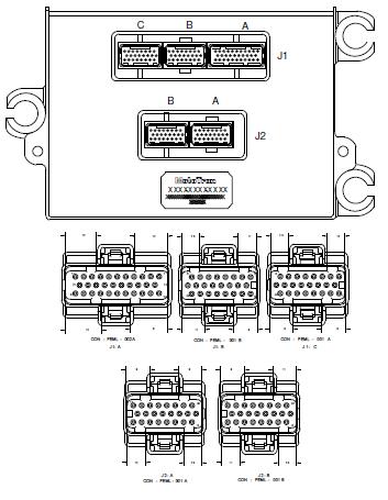
Connector Pinouts
Shutdown Behavior
The ECM565-128 requires continuous power on the BATT pin for controlled shutdown. If BATT is still powered, then the module can shut down and cut power via the Main Power Relay when KEY_SW is cut. It won't have controlled shutdown ability if BATT is cut on key off, since BATT is the only way to power the module. This behavior differs from the ECM-555 48/80 models, which can use DRVP to power the module in the event of ECUP power cut. (The 48- and 80-pin modules don't have a separate key-switch input.)
Boot Procedure
To boot the module, you use a boot key. The pin the boot signal goes to is J1-B7.
EST 13-16/Lamp 1-4 pins
The EST 13-16 pins on the 128-pin module can also be used as an LSD for resistance loads such as lamps. The max current that can be sunk is 1A. However, these pins have no fly back diode, which means they cannot drive any inductive or capacitive loads, including relays. If you want to use these pins to drive capacitive or inductive loads, you will need to add an external fly back diode. In such a case, it would be recommended to use a proper LSD pin.
HEGO End of Life
The ECM-565-128 L and C module will be released with the HEGO removed, WW p/n 8923-1977/8237-1448.
The ECM-565-128 H and F module continues in production. It does not have EGO/HEGO, but instead UEGO. WW p/n 8923-1572/8237-1237

