MotoHawk Hardware: Difference between revisions
| Line 199: | Line 199: | ||
Four of the pins can be used as DG5 to DG8 on the PROD module, and as KNK3 (2 pins) and KNK4 (2 pins) on the DEV module. | Four of the pins can be used as DG5 to DG8 on the PROD module, and as KNK3 (2 pins) and KNK4 (2 pins) on the DEV module. | ||
=== Purchase ECM-0563-128 === | |||
*[http://store.neweagle.net/ProductDetail.jsp?LISTID=80000107-1255227541 Purchase ECM-0565-128-H701-F00] | |||
*[http://store.neweagle.net/ProductDetail.jsp?LISTID=8000003D-1253646108 Purchase ECM-0565-128-H701-FOO-M] | |||
*[http://store.neweagle.net/ProductDetail.jsp?LISTID=80000105-1255227325 Purchase ECM-0565-128-L702-C00] | |||
*[http://store.neweagle.net/ProductDetail.jsp?LISTID=80000104-1255227278 Purchase ECM-0565-128-L702-C00-M] | |||
==ECM/GCM-S12-24 Part Number Changes== | ==ECM/GCM-S12-24 Part Number Changes== | ||
Revision as of 20:01, 14 June 2010
DataSheet Notes and Errata
MotoTron Line of Controllers and Specifications
Please visit the following MotoHawk ECU Summary Page for MotoHawk controller family availability. This is a good starting point to help select a family for which numerous part numbers can be found by searching the data sheets in the download section (login required, can be requested by sales @ (at) neweagle.net.
RoHS and MotoTron ECU Modules
Motorola had been pushing for RoHS compliance across the company since they are mainly consumer products, but when Conti took over there is no longer this push. There is no plan to go lead-free on solder for Visteon or Conti. The impact to the part design (higher reflow temps) and manufacturing is too great.
GCM-0563-048
GCM-0563-048-0801 (CCM48) Notes
- Note 1. The ANxM_DGxM pins may be configured as both analog and digital inputs at the same time; the intent is to allow the analog channel to be used for diagnostics of the digital channel. For these shared inputs, the DGxM time constant is 5.1 microseconds.
- Note 2. The 2.585k pull-down analog inputs have a 3k ohm pulldown in parallel with a 16.5k / 2.21k ohm voltage divider pulldown, with the Analog-Digital Converter such that:
- ADC_counts = ( 1024 / 5.00 ) * ( 2.21 / ( 2.21 + 16.50 ) ) * ( V_pin )
- or, 0 <= ADC_counts <= 1023 counts :: 0 <= V_pin <= 42.29 volts
- ADC_counts = ( 1024 / 5.00 ) * ( 2.21 / ( 2.21 + 16.50 ) ) * ( V_pin )
- Note 3. Relationship between ECUP Analog-Digital Converter counts and KEYSW voltage for GCM-0563-048-08xx and HCM-0563-048-08xx:
- ADC_counts_ECUP = ( 1024 / 5.00 ) * ( 2.21 / ( 2.21 + 16.50 ) ) * ( V_keysw - 0.7 volts )
- Please note that the default Main Power Relay block setting of 100 ADC counts corresponds to approximately KEYSW = 4.8 Vdc.
GCM-0563-048 Datasheet (36303) Known Errors
- Page 5 calls out DRVP as pin A23, which shows up as LSO7 in pages 4, 6 and 10
- Page 5 assigns Pin A15 to STOP whereas other pages assign B23 to STOP and A15 to AN13M/DG5M
- CAN1- appears to have quite a few redundant pins – A11, B11 and B21 (Pages 9 & 10)
Current Sense Capability for GCM-0563-048
- The GCM-0563-048-0801 (CCM48) module has current sense on H1+ (high side only).
- The GCM-0563-048-0802 (SIM48) module does NOT have current sense (either side).
Purchase GCM-0563-048
ECM-0563-048
Knock Inputs on the ECM 48
ECM563-48-0702 (for Mercury) had knock but that model never was released. The PCB still has the pads but it’s not populated on any active models. If there was demand, we could create a version with knock.
Purchase ECM-0563-048
- Purchase ECM-0563-048-0701-C-M
- Purchase ECM-0563-048-0701-F
- Purchase ECM-0563-048-0701-F-M
- Purchase ECM-0563-048-0704-CP2-M
- Purchase ECM-0563-048-0704-F
- Purchase ECM-0563-048-0705-CP0-M
- Purchase ECM-0563-048-0705-F
- Purchase ECM-0563-048-0806-CP0-M
- Purchase ECM-0563-048-0806-F00
ECM-0555-048
ECM-0555-048 (36301) Know Data Sheet Errors
- Page 1 of ECM-0555-048 Faimly of Engine Control Modules data sheet shows two(2) CAN 2.0B channels when it should show 1 CAN 2.0B channel and 1 RS485 Channel as of 4/13/2010
ECM 555-48 Part Number Changes
ECM-555-48-0710 replaced the ECM-555-48-0403
ECM-5554-112
ECM5554-112 E-Stop
The Fuel Pump Relay Driver (FUELPR) is not disabled after a STOP assertion (pinout B-H3). Woodward has confirmed the issue and is working on the solution.
ECM5554-112 RoHS or ELV Compliance
The PCM0904 is compliant to the current ELV (End-of-Life Vehicle Directive) requirements, not RoHS. Note, RoHS applies to consumer electronics products, and ELV is still the applicable directive for automotive parts. Again, this module is fully compliant to ELV and can be sold in Europe.
ELV Compliant End of Life Vehicles (ELV) Directive 2000/53/EC requires that certain automotive products be free (except for trace impurities) of mercury, cadmium and lead as of 2003-7-1. Lead can still be used as an alloying additive in copper, steel and aluminum and in solderable applications. These products comply with the ELV directive.
EU RoHS Compliant Restrictions on Certain Hazardous Substances (EU RoHS) Directive 2002/95/EC requires that certain electrical and electronic products be free (except for trace impurities) of mercury, cadmium, hexavalent chromium, PBB, PBDE and lead as of 2006-7-1. Certain exemptions are allowed such as lead used as an alloying additive in copper, steel and aluminum. These products comply with the EU RoHS directive. These products also comply with the ELV directive. Note that as of July 1, 2008 products that are shown as RoHS compliant do not contain decabromodiphenyl ether.
General Purpose Use of Knock pins
The knock sensor pins are dedicated, and have no alternate purpose other than Knock detection. One exception is that this circuitry is known to be used as a hardware "notch" filter.
Powering the ECM-5554-112-0904 (PCM0904)
The 112-pin modules are nominal 12-volt:
- VBATT (min) = 4.5 volts (crank transient) and 6.3 V (continuous).
- VBATT (normal) = 9-16 volts.
This voltage is expected at the BATT, BATT2, KEYSW, DRVG1, DRVG2, fuel injector, H-bridge, low-side drivers.
Specifics:
High Voltage Operation The following voltages are to be measured at the BATT pin, referenced to the PWRGND pins. Jump Start. The module shall operate normally when exposed to 24 volts for 5 minutes at an ambient temperature of 23 degrees Celsius.
Reverse Battery Connection
The module shall not be damaged by 5 minutes of reverse battery (-12 volts). This is a system level test and assumes a correct harness is in use. Specifically, it is assumed that the main power relay will be off.
Abnormal Connections
The module shall not be damaged from short-to-ground, short-to-battery, or intermittent open-circuit faults on any I/O signal. The following signals are excluded from this requirement since they are inherently a short circuit:
- PWRGND (not protected from short to battery).
- DRVP (not protected from short to ground).
- XDRG (not protected from short to battery).
- GNDREF (not protected from short to battery).
Note: For purposes of test, it may be assumed that DRVP is applied to the system prior and during the abnormal connection test.
Frequency (Speed) Inputs Notes
SPEED1 (B-G2), SPEED2 (B-H2), SPEED3 (B-H1) logic thresholds and hysteresis are software configurable.
SPEED1 - This input is normally used to resolve a variable frequency digital speed signal. Software shall be capable of selecting either a high impedance mode for 0 to 5 volt sensors or a 1 kilo-ohm pullup to 5 volts for open-drain type sensors.
SPEED2 and 3 - This input is normally used to resolve a variable frequency digital speed signal. The sensor shall provide a 0 to 5 volt signal. Note, the sensor is expected to be a low-side driver with internal pull-up to 5 volts of ~ 4.7 k-ohms.
Differences between the 0902 and 0904
Here is the full list of changes from PCM0902 to PCM0904.
1) Remove the H1 H-Bridge and replace with two Infineon BTN7930 ½ Bridge devices.
2) Remove the H2 H-Bridge and replace with two Infineon BTN7930 ½ Bridge devices.
3) Remove the On Semi NIF5002 Injector Drivers and replace with the On Semi NCV8403.
4) Remove the TACHLINK transistor (PZT3904) and replace with BFN38 device.
5) Routing of case ground traces to pin B-C3 (replaces CAN2 shield pin).
The new H-Bridges are more capable than the older parts and can be run at up to 10A depending on total ECU power dissipation. The injector driver change allows the option to run 2 injectors per driver (2A max) but again power dissipation must be considered. The TACHLINK change was to address robustness to transients.
CAN Shielding Differences Between 0902 and 0904
For ECM-5554-112-0902 (PCM0902): CAN_1 is not shielded, not internally terminated. CAN_2 is shielded, not internally terminated. CAN_3 is shielded, internally terminated 120-ohm.
CANSHIELD2 and CANSHIELD3 are available for shielded bus connections on the respective busses. The internal connection to the PCM ground consists of a 1 ohm resistor in series with a 10 nano-farad capacitor (i.e. no dc path). CAN shielding is not always standardized and this implementation may or may not be appropriate for any specific application.
For ECM-5554-112-0904 (PCM0904):
CAN_1 is not shielded, not internally terminated.
CAN_2 is not shielded, not internally terminated.
CAN_3 is shielded, internally terminated 120-ohm.
CANSHIELD3 is available for shielded bus connections. The internal connection to the PCM ground consists of a 1 ohm resistor in series with a 1 micro-farad capacitor (i.e. no dc path). CAN shielding is not always standardized and this implementation may or may not be appropriate for any specific application.
For the PCM0904 model, pin B-C3 was changed from CAN2 SHIELD to CASEGND. For typical applications, the CASEGND pin should be left not-connected.
Note the change in capacitor value for the shield between PCM0902 and PCM0904.
0904 Models without XDRP1 Capacitor
Difference between VP9DVU12A650-AA and VP9DVU-12A650-AB
VP9DVU-12A650-AA lacks a 10nF ESD capacitor on the XDRP1 (5V sensor supply) at J1C-D4. The lack of this capacitor leaves the module susceptible to radiated noise coupled onto the application harness. The coupled noise can cause instability in the XDRP1 voltage supply or module resets. Vehicle EMC issues were experienced during Free Field testing at approximately 23V/m and 140-180MHz.
To avoid the issue, the XDRP1 output should be disconnected from the wiring harness. If the XDRP1 output is required, a ferrite choke can be used to filter the noise. Placing a FairRite 43 material solid ferrite or Steward 28 clamp ferrite on the harness wire leading to XDRP1 within one inch of the mating connector will resolve the issue.
VP9DVU-12A650-AB incorporates a very small change to the PWB connecting a 10nF capacitor to the XDRP1 J1 pin making the module immune to radiated and coupled noise.
Purchase ECM-5554-112
ECM-0565-128-07xx-F/C
Supplementary Details to Datasheet
"ECM-0565-128-0701-C_ps36320_rev01.pdf" and "ECM-0565-128-0701-F_PS_36321.pdf"
ECM-0565-128-0702-CP0 is a minor rev of ECM-0565-128-0701-CP0. Same datasheet applies to both.
There are a few errata on this datasheet. To clarify:
ECM-0565-128-L701-Fxx, flash (no calibratible memory) "PROD" production module. ECM-0565-128-L70x-Cxx, calibratible "DEV" module.
Woodward part# 8237-1237 rev. NEW == ECM-0565-128-0701-F (PCM128 "PROD") Woodward part# 8237-1238 rev. A == ECM-0565-128-0702-C (PCM128 "DEV")
The PCM128 modules are nearly identical. The "PROD" -F module has 4 extra analog inputs and 4 extra digital inputs; the "DEV" -C module has 2 wide-band oxygen (lambda) sensor inputs and 2 extra knock channels, as well as additional RAM. For the 2007 model-year, these modules have three H-bridges: 10-amp continuous, 12-amp peak. (The datasheet is being updated to reflect the higher-ampacity capability of H1 and H2, due to board layout revision.)
General Comments:
The low-side fuel injector drivers INJx may be run as 3A peak / 1A hold (all 12 injector drivers), or 7A peak / 3A hold (6 drivers as indicated). Use the "Injector Current Select" block in the MotoHawk Advanced Digital I/O library to select.
The fuel injector drivers INJx and LSDx low-side drivers may be used as PWM outputs or as discrete outputs. These outputs act as a switch to ground. When the MOSFET is ON, the module resource pin is connected internally to the module DRVGx driver ground pins.
The maximum current rating for the ECU terminal pins is 10 amps continuous. However, most circuits have a lower current rating depending on the type of circuit connected inside. These ratings are shown on the ECU datasheet.
For the analog and digital input circuits, the actual current draw is dependent on the wiring connections. Generally, these are either sensor transducer inputs, or potentiometer / thermistor / RTD resistive devices forming a voltage divider with the internal pull-up or pull-down circuit.
Knock circuitry difference on the Calibration (Dev) and Flash (Prod) Units
Four of the pins can be used as DG5 to DG8 on the PROD module, and as KNK3 (2 pins) and KNK4 (2 pins) on the DEV module.
Purchase ECM-0563-128
- Purchase ECM-0565-128-H701-F00
- Purchase ECM-0565-128-H701-FOO-M
- Purchase ECM-0565-128-L702-C00
- Purchase ECM-0565-128-L702-C00-M
ECM/GCM-S12-24 Part Number Changes

Customer my download datasheets form the DOWNLOADS section located under the Naviagtion Toolbar on the left hand side of this screen. If you are a customer, use the same login used for the webstore. If you do not remember your login please send a request to: support@neweagle.net
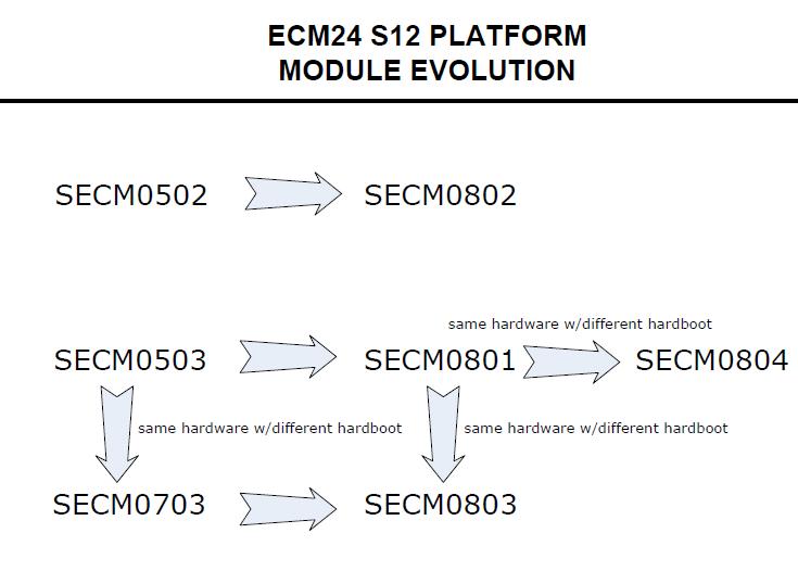
- The SECM0502 is obsolete, replaced by SECM0802. These modules are functionally equivalent.
- The SECM0503 is obsolete, replaced by SECM0801. These modules are functionally equivalent.
- The SECM0804 is a "made" part, created from an SECM0801 with a different general-purpose hardboot loader.
- The SECM0703 is obsolete, replaced by SECM0803.
- The SECM0703 is a "made" part, created from an SECM0503 module with a customer-specific hardboot loader.
- Likewise, the SECM0803 is a "made" part, created from an SECM0801 module with that same customer-specific hardboot loader.
Notes on the ECM-S12-24 part number migration
There is different hardboot software installed b, but the physical hardware is identical. SECM0801 (SECM0503) "HB V1P2" hardboot CityID 129 = 0x81 SECM0804 "HB_4_3_RC1_PROD" hardboot CityID 11 = 0x0b I am unfamiliar with differences between these two hardboot versions, except for the hardboot CityID.
The reason for the OEM part number changes, e.g. from SECM0503 to SECM0801, is typically due to changing internal components (replacing a transistor that is end-of-life with a new, equivalent, transistor) or similar issue. However, externally-visible functionality is expected to be the same: same ADC pull-up values, etc.
Thus, the inputs/outputs are the same for SECM0503 / SECM0801 and SECM0804.
We have Woodward part numbers for all products, but please work with the quote team to make sure you get what you need. Of course, the tech support team can help, as required.
Woodward Part Number Description
1751-6422 ECM0S120240503CP0
8923-1574 ECM0S120240503CP0-M
1751-6425 ECM0S120240801CP0
8923-1575 ECM0S120240801CP0-M
1751-6426 ECM0S120240801F00
8923-1576 ECM0S120240801F00-M
1751-6431 ECM0S120240804CP0
8923-1582 ECM0S120240804CP0-M
1751-6432 ECM0S120240804F00
8923-1583 ECM0S120240804F00-M
General Hardware / Wiring Questions
Voltage Specifications for Modules
While all the modules are designed to withstand momentary short-to-battery on the input sensor pins (except those that inherently cannot be protected), the hardware validation test is typically 1 minute short-to-battery.
In the case of analog and digital inputs (nominal 5-volt), the circuit may not be able to dissipate heat when connected to a higher voltage on a longer timeframe. For instance, the pull-up or pull-down resistor may not be sized to dissipate heat from that higher voltage (resistor wattage rating).
+++++
For the circuits marked "16V okay" in the table below, the resistor wattage rating is such that continuous operation at 16V should be okay.
"Double Battery" situation: If there is a particular circuit, let me know and we can check. At nominal 24V (as high as 32V jumpstart), the trace widths as well as the PU/PD resistor may be vulnerable. Some of the pull-downs would likely be okay, but this should be verified. For example, AN4: 220k-ohm pull-down ---> P = V2 / R = 32*32 / 220e3 = 0.005 W = 5 mW. The resistor for AN4 is rated 63 mW. Depending on ambient temperature for module (heat transfer from resistor, to module body, to ambient), this circuit may be okay for short "double battery" exposure.
H-bridge Wiring
The H-bridge is normally wired as: (H+)----(load)----(H–) and the H-bridge circuit is powered from DRVP internally. (BATT)----(MPR Common, MPR Normally Open)----(DRVP)----(to H-bridge and other internal devices, and flyback diodes). The low side of the H-bridge circuitry connects to DRVGx and then back to battery ground.
ECM Differences
| MotoHawk Target | Current MotoTron part numbers (What to ask for When Ordering) | |
| ECM-0555-048-0706 | EC-0555-048-0701 (-0706 not produced, replaces -none-) | <--VR crank |
| ECM-0555-048-0707 | ECM-0555-048-0707 (-0702 no produced, Replaces -0402) | <--VR crank |
| ECM-0555-048-0708 | ECM-0555-048-0708 (-0703 not produced, replaces 0401) | <--Diital/Hall crank |
| ECM-0555-048-0709 | ECM-0555-048-0704 (0809 not produced, replaces -0401) | <--VR crank |
| ECM-0555-048-0710, | ECM-0555-048-0710 (-0705 not produced, replaces -0403) | <--VR crank (either |
| ECM-0555-048-0403 | MH target should work) | |
Implementing J1587 Protocol on a J1708 hardware layer (using a MotoTron RS485 Driver)
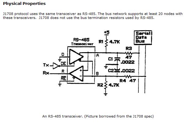
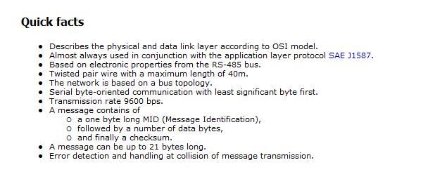
A RS485 software driver in MotoHawk can be written for J1587. The hardware signal conditioning and some general J1587 notes follow:

