Raptor VeeCAN: Difference between revisions
No edit summary |
No edit summary |
||
| Line 43: | Line 43: | ||
==Raptor VeeCAN Example== | ==Raptor VeeCAN Example== | ||
<p>The image below is | <p>The image below is a basic Raptor VeeCAN project. It demonstrates separation of HMI logic from the control and signal logic This is a stylistic approach to ensure easy transferability of logic to and from other Raptor platforms that do not have HMI functionality.</p> | ||
<gallery widths=700px heights=300px perrow=7 caption="Raptor Display Project"> | <gallery widths=700px heights=300px perrow=7 caption="Raptor Display Project"> | ||
File:ExamplePROJECT.png|Example design, separation of HMI and controls logic is visible | File:ExamplePROJECT.png|Example design, separation of HMI and controls logic is visible | ||
Revision as of 16:31, 6 February 2015
Return to the main Raptor page
Overview
The Raptor™ VeeCAN platform is a Simulink toolset for development on the VeeCAN 320 Display. Models built for VeeCAN using the Raptor framework are highly transferrable to other modules in the Raptor family. Raptor VeeCAN enables development of its graphical display and the five user action buttons. This allows for rapid development of a Human Machine Interface (HMI).
VeeCAN Libraries
For information on the blockset libraries that support VeeCAN, Go Here
Inputs and Outputs
The following is a list of the I/O on the VeeCAN:
- (2) CAN
- (1) RS-232
- (1) Tachometer Input
- (7) Analog Inputs
- 0-10VDC
- 0-2.5VDC
- 0-500mA
- (2) Digital Inputs
- (4) Digital Outputs
CAN Development
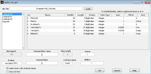
CAN development within the Raptor framework integrates industry-standard DBC files. This allows for quick sharing of a CAN protocol both within and outside the Raptor framework. The image below shows the configuration screen of a CAN Rx message block after a DBC file is selected.
- Raptor CAN GUI
-
Configuration of a CAN receive block with a loaded DBC file
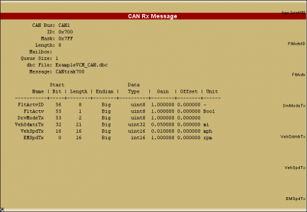
Selection of a CAN automatically populates signal output specifications on the Raptor CAN message blocks with the information contained in the DBC file, as shown in the image below.
- Raptor CAN Block
-
View of a CAN receive block after selection of a CAN message from a DBC file
New Eagle's OWL is a comprehensive CAN tool, useful for sending and viewing CAN traffic.
Interested? Read more on OWL here.
Raptor VeeCAN Example
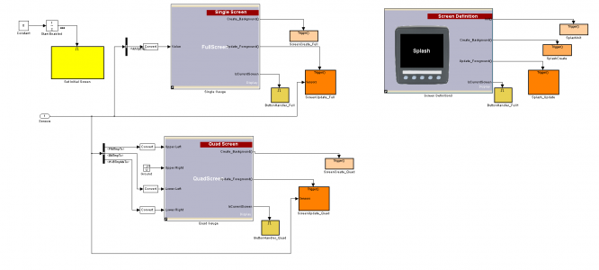
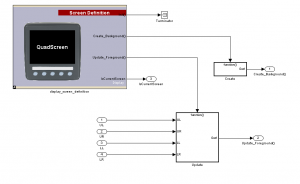
The image below is a basic Raptor VeeCAN project. It demonstrates separation of HMI logic from the control and signal logic This is a stylistic approach to ensure easy transferability of logic to and from other Raptor platforms that do not have HMI functionality.
- Raptor Display Project
-
Example design, separation of HMI and controls logic is visible
- Click here to learn more about our Raptor Platform!
- Click here to see some Raptor Example Displays!
VeeCAN Display Development
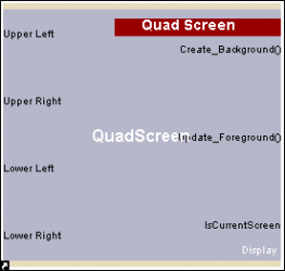
The Raptor HMI blocks were designed both to allow ease of use and to allow low-level control of display features. In the RVC library you will find high level blocks to quickly display an assortment of information and graphics, such as: lists, menus, gauges, images, and text strings. These high level blocks have been designed from a primitive block set, meaning that tweaks can be made to these under-the-covers primitives to configure the display to your taste, or to help you create your own display screens from scratch. The images below demonstrate a gauge block and a subset of the primitive blocks within it.
- Raptor Display Blocks
-
Gauge blocks consisting of primitives
-
Primitive blocks within a gauge block
Simulation
The RVC simulator creates a strong link from the software development cycle to the hardware testing cycle. Typically these would be two distinct, time-consuming, phases, but, with strong coupling of the simulator and the hardware (hardware-in-the-loop simulation), and with real-time debugging, iteration time is drastically reduced.
