GCM70: Difference between revisions
(→FAQ) |
|||
| Line 38: | Line 38: | ||
===Calibrations=== | ===Calibrations=== | ||
In production programs, it is recommended to store all calibrations in Flash memory (available within the "raptor_target_def" block). | |||
===Recovery Procedure (Boot Key)=== | ===Recovery Procedure (Boot Key)=== | ||
Revision as of 13:53, 3 April 2020
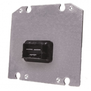
Raptor GCM70
The GCM70 is a general purpose control module. The module has 2 CAN buses, and sports a 3-phase motor driver. The eclectic inputs and outputs make this module suitable for a wide variety of general purpose applications.
The GCM70 is part of a family of rugged, automotive-grade production controllers that use a software development process based on MATLAB/Simulink, known as Raptor-Dev. Raptor-Dev significantly speeds up algorithm development by using automatic code generation. In addition, developers can quickly test application software on their PCs with a built-in onscreen PC simulation.
Variants
- GCM-5634M-70-1459
- GCM-5634M-70-1559
- GCM-5634M-70-1562
Datasheets
- GCM-5634M-70-1459
- GCM-5634M-70-1559
- GCM-5634M-70-1562
Pins and Crimping
Need to make a harness? Click here to get started.
Want to buy a pre-made harness? Click here to order.
Compiler
GCC PowerPC EABI 4.6.0 SPE
FAQ
Non-Volatile Memory Corruption
Non-Volatile memory can be corrupted during a write if the module is improperly powered off (ie removing power from Batt+ (Pin 68)).
Calibrations
In production programs, it is recommended to store all calibrations in Flash memory (available within the "raptor_target_def" block).
Recovery Procedure (Boot Key)
The GCM70 requires a Boot Key to recover the module. These can be found on our store page
The use the boot key to recover the malfunctioned module, please follow the Raptor-Cal MotoHawk Module Recovery steps provided: Boot Key Recovery and below.
Notes:
The Boot Key signal (Pin E on the Smartcraft connector) needs to be connected to the SWG4 pin for the GCM70.
Once the bootkey is used, the module will default to a CAN baud rate of 250k, so update the Raptor-Cal settings accordingly.
Power Cycle Instructions:
- Step 1: Remove all power to the module by turning off Key switch and then power supply. Connect the Boot Key to the bus.
- Step 2: From Raptor-CAL/Service: Select Program, then the recover check box, MotoHawk, Select the .RPG file.
- Step 3: Click OK, turn on power supply, then key switch.
For a full list of steps, see the Raptor-CAL FAQ Page
Bootstrap
The GCM70 can be forced to remain in the firmware bootloader by applying a bootstrap sequence. The bootstrap sequence is:
| Pin | State for Boot |
|---|---|
| AN1 | High |
| AN2 | High |
| AN3 | High |
| AN4 | |
| AN5 | |
| AN6 | |
| AN7 | |
| AN8 | |
| AN9 | Low |
| AN10 | Low |
| AN11 | Low |
Raptor™ GCM 70 Power Up Process
Raptor™ GCM 70 Power Up Process, a product review and development tutorial.
Difference Between 1459 and 1559 variants
Pins 39, 40, 41, 59, & 60 have different pull-up resistors
SPD1 Limit
The frequency speed limit in the SPD1 resource is designed for 10K.
