HCM-563-48: Difference between revisions
No edit summary |
|||
| Line 46: | Line 46: | ||
== Webstore == | == Webstore == | ||
'''[https://store.neweagle.net/product-category/products-by-category/controllers/ Webstore: All Control Modules]''' | '''[https://store.neweagle.net/product-category/products-by-category/controllers/ Webstore: All Control Modules]''' | ||
Revision as of 18:05, 6 April 2022

TVM Module
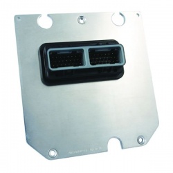
The HCM 563-48 0801 was also known as the TVM module as part of the Fire48 MotoTron Controller platform.
What is the difference between the I/O of the model 0801 and 0803
From the data sheet, the inputs differ on the pull up to power and pull down to ground resistor values.
Why does the HCM-563-48 modules have two DRVP pins when there are no high side drivers?
These modules have the DRVP pins because the HCM is meant to drive solenoid valves for hydraulic applications. Therefore the module has LSO pins that have a recirculating feature, so when the solenoid coils are losing current it has a path back to the power supply.
Module I/O
The VR+/ DG1 input can be used as a Digital Switch Input. When the pin is selected to do so, the DG1 pin has 51K pull down resistor.
Development Harness
-Their is a development harness for the GCM-0563-48 module, the HARN-ECM-014. This harness was however originally designed
for the GCM-0563-48 module, leaving a few issues when using with the HCM.
-Firstly, you do not have access to the pin A24, this is a ground pin in the GCM and is therefore tied into the ground
node.
-For the wire colors you cannot follow the information in the HCM-0563-48 datasheet, you need to refer to the HARN-ECM-014
datasheet. Just note that the block diagram in the harness documentation is a GCM. This means the pins information is not
for the HCM, just use the datasheet for wire colors.
Datasheet Errors
- The Datasheet shows that is a Knock sensor. The hardware is there for a Knock sensor but the software is not. This means that you cannot use the sensor with MotoHawk.
- For the HCM-0563-48-801 datasheet the AN16M_DG8M pin description seems to show the pin tied to ground. This is an error, it is a standard 150K PU input.
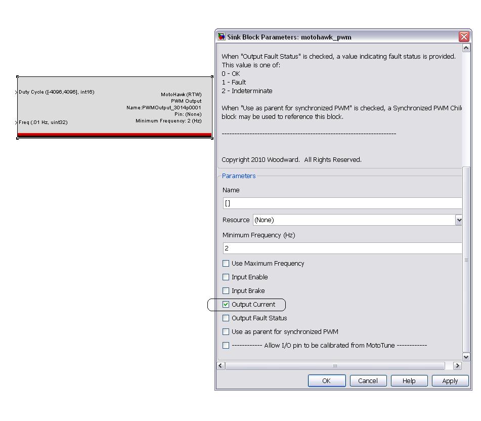
How do I access current feedback in this module?
If you double click on PWM block, and select the 'Output Current' checkbox from the list, it will give you a current in mA as an output. The following picture illustrates it.
Data Sheets
- HCM-0563-048-0801
- HCM-0563-048-0802
- HCM-0563-048-0803
