Raptor:Getting Started
New Eagle > Products Wiki > Raptor Platform > Raptor-Dev > Getting Started with Raptor-Dev
Getting Started
Installation
Prerequisites
- MATLAB/Simulink
- Raptor™ requires a compatible installation of MATLAB/Simulink in order to create models for code generation. MATLAB/Simulink release 2012a 32/64 bit and newer are supported. The following tools from Mathworks are required:
- MATLAB
- Simulink
- Embedded Coder
- MATLAB Coder
- Simulink Coder
- Stateflow (Optional)
- Raptor™ requires a compatible installation of MATLAB/Simulink in order to create models for code generation. MATLAB/Simulink release 2012a 32/64 bit and newer are supported. The following tools from Mathworks are required:
- Compiler
- To compile the generated code properly for your embedded platform, the appropriate compiler and associated license will be required.
- The BCM48, CM0711, CM3626, and CM2115 use the CodeWarrior for MPC55xx/MPC56xx Microcontrollers V2.10 compiler. You can download an evaluation version or purchase the compiler here.
- The CM3620 uses the IAR Embedded Workbench for ARM 4.42A compiler. To coordinate obtaining an evaluation version of the compiler please contact New Eagle Support.
- The GCM196 and ECM196 use the Hightec Compiler for the Infineon TriCore architecture v3.4.5.11 compiler. For more information on the GCM196 compiler, and to ensure you get the correct version please contact New Eagle Support.
- To compile the generated code properly for your embedded platform, the appropriate compiler and associated license will be required.
- .NET Framework
- Raptor requires the .NET framework from Microsoft that comes preinstalled on most current version of the Windows platform. If this is not installed prior to running the Raptor installation program, it will be downloaded (internet access required) during the installation process.
- If necessary, the .NET framework can be downloaded manually at: www.microsoft.com
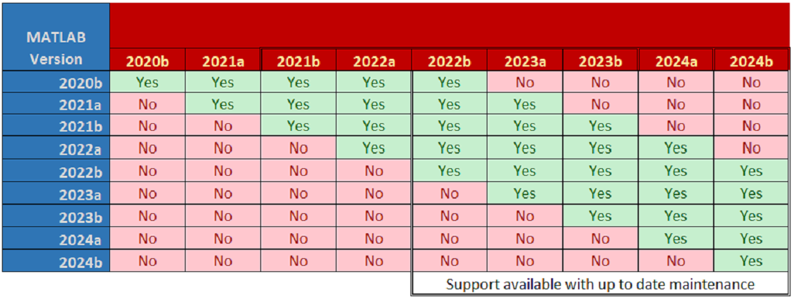
MATLAB Version support
Raptor currently requires Windows 7 (32 or 64 bit versions) and MATLAB 2012a+
Installation
- Download and run the latest Raptor installer program
- Follow the instructions and change the options to your liking
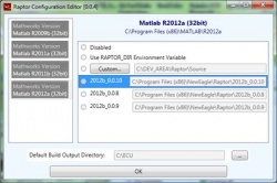
- When the installer finishes, run the 'Raptor Configuration Editor'
- This shows which versions of MATLAB and Raptor are compatible
- Set the configuration settings for your version of MATLAB
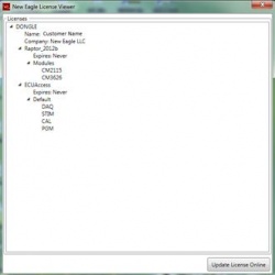
- Verify your Raptor License
- Open the Start menu and go to "New Eagle -> New Eagle License Viewer"
- From the MATLAB command prompt, type >>raptor_check_license
- Verify MATLAB/Simulink Integration
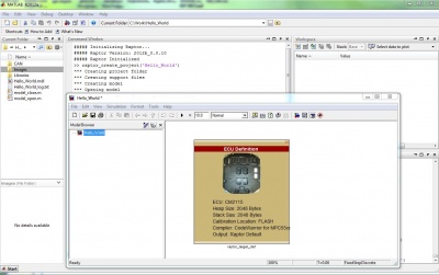
- When Raptor has been properly integrated, you will see the following message upon starting MATLAB:
Software/Code-Generation
Creating a Sample Raptor Project
The easiest way to create a new Raptor project is to use the 'raptor_create_project' script from the command prompt. This script will create a new project with the appropriate code-generation settings for Raptor. The new project will have a few useful folders where you may want to store project files in the future (CAN, Images, Libraries). These folders are automatically added/removed from the path when the model is opened/closed via the model_open/model_close scripts that are generated alongside the model (mdl) file.
- Open MATLAB and in the command prompt type >> raptor_create_project
- This will create a new project with the appropriate settings for Raptor
- Select the proper target with the ECU definition block
- Build the project by pressing 'CTRL + B' or select 'Tools->Code Generation->Build Model'
- If successful, a message indicating so will appear in the command window
- The output files will be created and placed (by default) in C:\ECU
- You may now flash your software onto the controller using tools such as Raptor-Cal
Programming Setup for Raptor Modules
Basic Programming Procedure
1. Install Raptor-Cal
During the Raptor-Cal installation, an ECU folder is created on the C: drive of the computer, with the following folders:
- RPG for Raptor Package (.rpg) files
- RDIS for display (.rdis) files
- RCAL for calibration (.rcal) files
Please read the Raptor-Cal/Raptor-Service User Guide for detailed instructions on downloading and installing Raptor-Cal.
2. SmartCraft Hub Setup
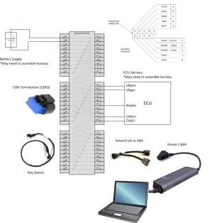
Connect the following components to the SmartCraft hub
- Battery/power supply (+12V or +24V)
- Key switch
- CAN termination resistor (120 ohms) on CAN1
- Kvaser USB-to-CAN device (connect to the laptop/PC) to CAN1
- ECU harness
Ensure that your setup includes the following:
- Make sure that battery power goes across pins A (+) and B (-)
- Check for continuity between pins A and F with key switch turned ON
- Check resistance across pins J and K (should be 120 Ohms if termination is connected)
- Ensure that the ECU harness has pins A, B, F, J, and K populated to account for power, ground, key switch, and CAN1. See image below
3. Raptor-Cal Programming Procedure
You will need to have a program file compiled to program. This is the .rpg file that is generated after a successful build. The file is located in the RPG folder.
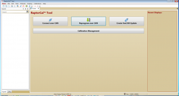
- Open Raptor-Cal
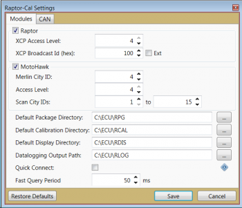
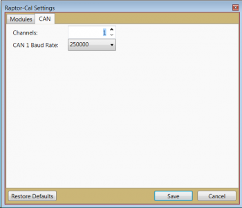
- Make sure that the port setting is set to the correct baud rate and XCP settings that was last flashed/programmed onto the module. Please note that the port should be set to XCP Access Level = 4, XCP Broadcast ID (hex) = 100, and 250kbaud for a module brand new out of the package. To check the port settings in Raptor-Cal, go to Edit -> Settings.
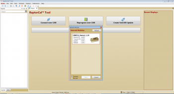
- If all of the settings and setup are correct, turn on the ECU and click "Reprogram over CAN"
- Select your module, then select the program you wish to flash onto the module
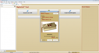
- Raptor-Cal will begin reprogramming the module
BCM48 Programming Procedure
IMPORTANT: The model that is going to be programmed on to the BCM48 must have its CAN1 set to 250kbaud
1-2. Programming the BCM48 follows the first 2 steps of programming any other raptor module.
3.Configuring the Local Area Network connection
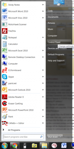
- Click on the start menu and click control panel
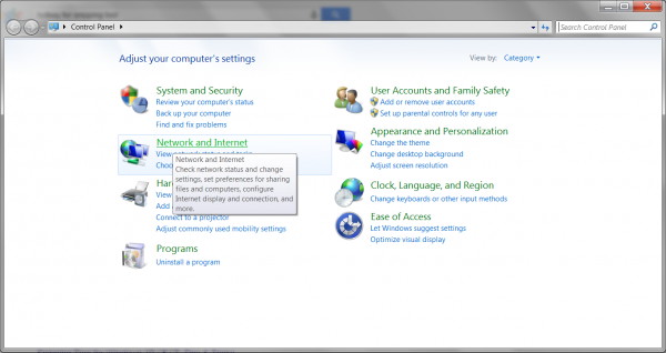
- Click on network and internet.
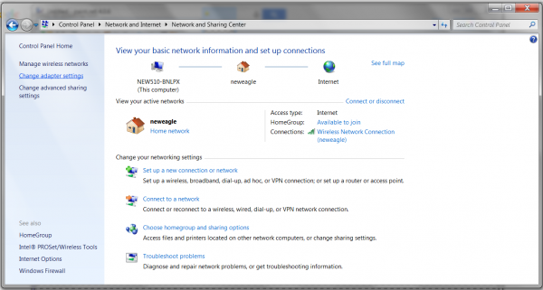
- Click on change adapter settings
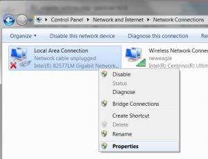
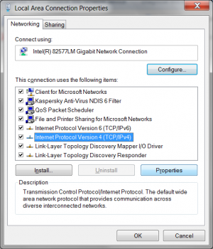
- Right click on Local Area Connection and chose properties from the drop down list
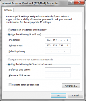
- Select Internet Protocol Version 4 (TCP/IPv4) and click properties
- select "Use the following IP address"
- enter 193.168.1.1 for the IP address
- the subnet mask should auto populate, if it doesn't enter 255.255.255
4. Ethernet Programming Procedure
- connect the Ethernet signals from the BCM48 to the ether net adapter on your PC.
- navigate to the build folder that was used to build your raptor module.
- double click on the Flash.Bat file that was generated when the model was built.
- this should open up the command prompt and begin programming the BCM 48
- a confirmation message will be displayed when programming is complete.
- the BCM48 is now ready to communicate via CAN and can be used for display and calibration applications in Raptor-Cal.
