Raptor-Dev-Vector-CANape-Support
Vector CANape
The following information is also contained in PDF format: Using Vector CANape with Raptor (PDF)
This information is also included in the 'Documentation' folder of the installation directory for Raptor-Dev.
Steps to build A2L files for Vector CANape
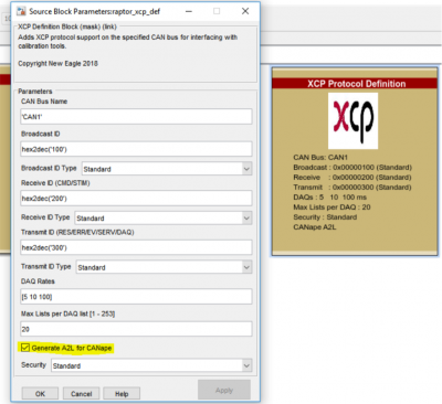
- From the project home page, double click on “XCP Protocol Definition”
- Mark “Generate A2L for CANape” true
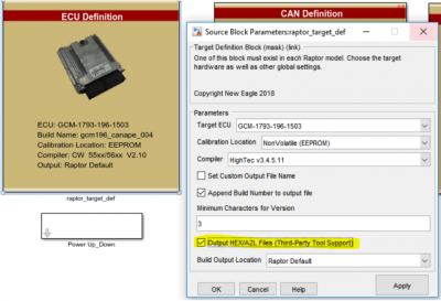
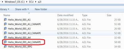
- Once the option is checked, Vector CANape a2l file will be created automatically during the build process and placed at C:\ECU\a2l. The a2l file contains information about the built application such as details about measurements and adjustments. Using this file, you can connect to the programmed ECU to view live data and make calibration adjustments.
- In the image above you will notice that there are 3 extra files created labeled “…_CANAPE”. This is because the model that caused these files to be generated contained parameters with access level 1 and 4. The file for access level 1 ends with ‘_A1’ and contains only those parameters for access level 1. The file for access level 4 ends with ‘_A4’ and contains parameters defined with access level 4 or lower (e.g. all parameters.)
Initial Setup with Vector CANape 14.0
- Open CANape, then select “<Create new project>”
- Name the project
- Choose the destination for the project
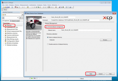
- Once a project is created right Click on "Devices"
- Click on New Device from > 'Click Database'
- Select the a2l file with “projectName_A4” type from C:\ECU\a2l
- Check the "Activate dataset management" true > click "Next"
- Select the corresponding CAN channel from the drop down menu under "Channel:"
- Click "Next", no changes needed yet for the Map File Settings, click "Next" again
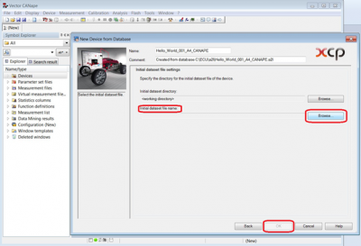
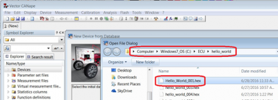
- Click on browse, and select the .hex file found C:\ECU\project_name
- Note: This files was created during the Raptor build
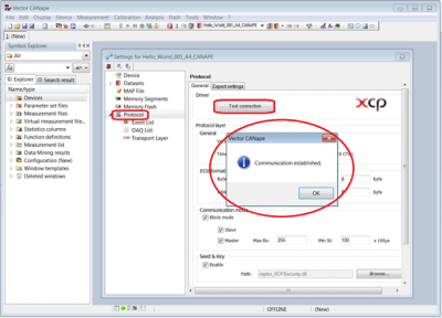
- Once selected, click OK. A window for settings will pop up automatically. Click on “protocol” from the menu on left and click on “Test connection”. This will verify if the project is connected with the ECU in order to run necessary tests.
- Note: If there is an error, please check if Baud rate is correct.
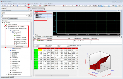
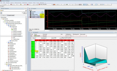
- Press “OK” once communication is established. Now from the explorer on the left, click on the “device name” > Datasets\.. > “project name” > “parameter of interest”. Drag and drop the parameter onto the right.
- Click on the “Flash” icon highlighted above. It will take CANape online with the ECU connected. The selected parameters will be updated with real-time.
Merging Offline Calibration Changes
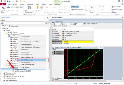
- Once you have made offline changes or opened your calibration file, explore in the 'Device_Name > Datasets' directory
- Right click on the dataset of interest, then click "Save dataset as"
- Choose destination and click "Save"
- Open New Eagle's 'Raptor-Cal'
- See Raptor-Cal for more information
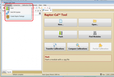
- Click 'Program' > 'Create Raptor Package'
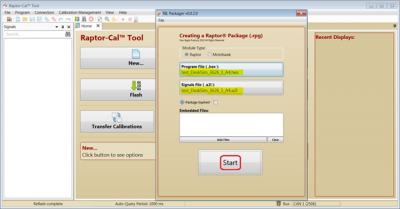
- Click on 'Program File (.Hex) and navigate to your new .hex file with offline calibration
- Click on “Signals File (.a2l)” and navigate to the corresponding .a2l file under C:\ECU\a2l.
- Click 'start'
- Save the .rpg file created
- Close the Raptor Package program
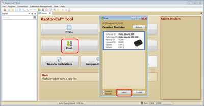
- Navigate to the 'Raptor-Cal' homepage and click 'Flash'
- Once the module (ECU) has been detected, click 'Select'
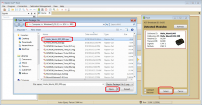
- Navigate to C:\ECU\RPG and open the .rpg file saved from using the Raptor Package program
- Once the file is opened, it will automatically flash the ECU with offline calibrated changes
Steps to verify the offline calibration changes
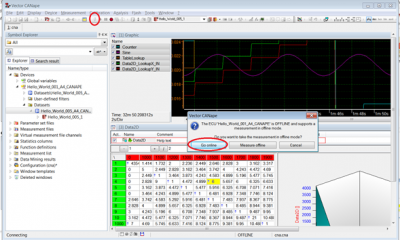
- Go to the 'Vector CANape' program and click the Flash' button to go online
- Click 'GO Online'
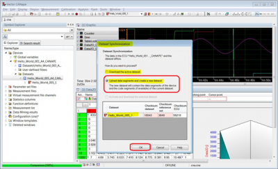
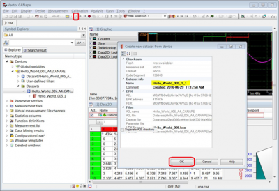
- Choose "Upload dad segments and create a new dataset"
- This will allow for the new calibrations flashed on the ECU to be synchronized with dataset that is on the hard drive.
- Click 'OK'
- Click 'OK' again
- Now once again click the 'Flash button' to be online
