Bench Tools
MotoHawk Control Solutions/Bench Tools
Breakout Assemblies
Performing ECM signal measurement and failure testing without modifying the harness can be difficult and time consuming. ECM breakout boxes are rugged harness inserts designed to make this painful job easy. Breakout boxes were designed by application developers to assist troubleshooting and failure mode testing activities and are a highly recommended part of every developer's toolkit. The family of breakout boxes covers the entire range of Woodward's MotoHawk Control Solutions modules. The breakout box plugs into the existing harness connectors and ECM, but also provides an extension with measurement points and circuit breaking bars. Each pin to the ECM can be probed, open circuited, or connected to any other signal. Each breakout box assembly comes with an Expander toolkit of patch cables, shorting bars, and banana jacks.
Webstore
Webstore: Breakout Box Assemblies
Connector Crimp and Removal Tools
Includes tools that are designed to strip, cut, crimp, and remove wire.
Webstore
Webstore: Connector Crimp and Removal Tools
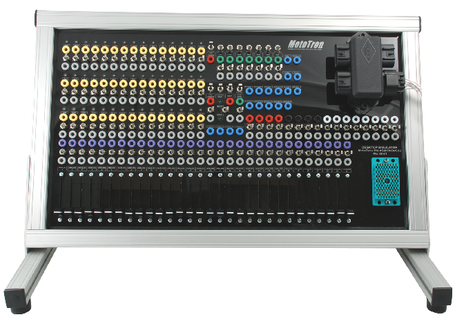
MotoHawk Desktop I/O Simulator
The MotoHawk Desktop I/O Simulator is a handy tool for bench development and testing. It allows you to adjust analog input levels with potentiometers, monitor output, test application scenarios, etc, without needing actual sensor connections. The MotoTron Control Solutions wiki has more information. If you are interested, please contact sales@neweagle.net. The part number is ASM-CNDV-002.
Webstore
Webstore: MotoHawk Desktop I/O Simulator

The Desktop I/O Simulator is designed to assist in developing control programming for a MotoHawk ECM; this practical device enables you to more easily simulate and adjust analog input levels (via onboard potentiometers), monitor output, test application scenarios, etc., without requiring the actual sensor connections. The Simulator has I/O, CAN connections, power and ground channels, keyswitch, and other features as applicable, which map to the respective resources of the ECM in use. Connect the MotoHawk ECM to the Simulator, using the appropriate available harness. Connect a computer with programming and calibration tools to the ECM via CAN or RS485 connection to the mounted CAN junction box, or floating connectors. Then use the Simulator to adjust input levels, drive output loads, monitor I/O signals, verify parameters, and as a result better understand and adjust the control programming needed, without using actual application hardware.
Specifications
- Aluminum frame, angle-mounted for ease of use, with scratch-free rubber feet
- Over 200 banana jacks in total for I/O - connect inputs or meters/oscilloscope to outputs
- 30 Channels of Analog Input (switchable - On / Off) with dedicated potentiometer sliders
- 45 Channels of Low or High Side Output (switchable - On / Off)
- 3 CAN Channels (switchable - On / Off)
- 1 RS485 Channel (switchable - On / Off)
- 8 Digital Inputs (switchable - On / Off or pulled High / Low)
- 10 Power and Ground Channels (switchable - On / Off) , including ECM Input Voltage+/-, XDRP, XDRG, MPRD, DRVP, DRVG, and Key Switch
- 4 Knock sensor inputs
- 4 CAM/Crank inputs
- 11 Non-assigned banana jacks
Depending on the ECM resources available, some of the jacks may not be mapped or connected to any resource from the ECM. Refer to the datasheet for your particular ECM to determine the resources available. It is best to check and verify the presence of the intended Simulator/ECM resource before attempting to apply in a test scenario.
Setup
Make the following connections:
- SCF: Plug connector labeled SCF on the back of the simulator into the 4-way junction box on the front of the simulator
- Power Cable:Plug the power supply cables on the back of the simulator into your power supply.
- CAN: Connect your CAN or communications cable (sold separately) into the Simulator 4-way Junction Box.
Optional Connections:
- SCM: Optional connector for external key switch
- Serial: Optional connector for external serial communications