Delphi
Delphi DC-DC Converter
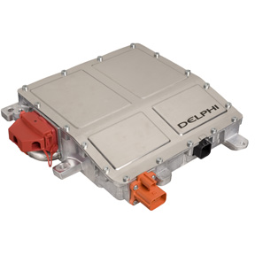
Delphi Universal 2.2kW DC/DC Converter creates DC voltages in hybrid and electric vehicles necessary to power accessories and the HVAC system. Liquid-cooled, the DC-DC converter operates at input voltages from 216 to 422VDC with a power range to 2.2kW.
Benefits
- In production
- Proven automotive design, reliable even in the harsh environment of the engine compartment
- Highly efficient conversion using synchronous rectification
- Applicable to multiple vehicle platforms without re-engineering
Features
- Analog output voltage is adjustable through CAN serial communication; 11V – 15.5V
- Bi-directional capability supports charging of high-voltage battery
- Over-voltage, over-current, and over-temperature protection with fault reporting
- CAN serial interface
Webstore
Switch Application that does not require CAN messages to and from the DC-DC converter
Several customers have shown interest in using the DC-DC converter without a CAN based controller. The DC-DC does require CAN messages and New Eagle's Switch application offers the customer to use the product with a physical switch using our controller.
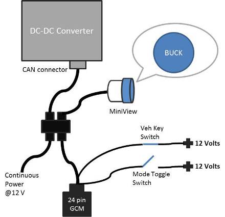
In our application, the customer can charge the HV Battery while the Vehicle Key switch was open, or the vehicle turned off. This generally translates into a addition of a mode toggle switch that would control the mode of operation of DC-DC converter (Buck or Boost or Standby). We offer a turn key app embedded in a GCM 24 pin S12 module, that hooks up to the DC-DC converter and a small display called MiniView, that helps user control the DC-DC converter mode as well as see the active mode on the display. The following sketch shows how these components may be connected in a typical scenario.
Note: New Eagle can modify any of these functions per your specification.
CAN Library
A DBC file containing the CAN messaging necessary to use the DC-DC converter can be purchased. To purchase the item on the Webstore go to this page, DC-DC Library.
Mounting Information (Vibration Dampening)
There are no "dampening feet" used with our DC/DC Converter. In most cases where a vehicle manufacturer has used this, it has been mounted underhood, out of the splash zone, and typically on a frame or bracket.
This bracket utilizes the mounting bosses per the description in the U2C Customer Manual (i.e., bolt size and thread type, grounding cable location, etc.). In many cases the bracket itself is attached to the engine, but the U2C is never directly attached to the engine.
The U2C has been validated to operate at underhood temperatures and with a vibration profile commensurate with being on a frame attached to the powerplant. Using it in that manner should preclude the need for any type of additional "dampening".
Cooling Notes
The U2C is robustly protected from "over temp" conditions. There are two thermistors on our product. One measures inlet coolant temperature ("heat plate temperature"), the other measures the temperature of the electronics ("14V temperature"). When the heat plate temperature reaches 85°C we set a fault. To protect the converter we begin to "de-rate" its output (reduce available power) when the temperature reaches 87°C. If the heat plate temperature should reach 105°C we will shut down the converter. It will start up again in a "de-rated" mode when the temperature falls below 100°C and the "14V Enable" (a requirement for initially going into conversion - see the 1D7 message, "Enable/Set point request") is toggled.
If the electronics temperature reaches 95°C we also set a fault. "De-rating" due to the electronics temperature begins at 95°C, and shut down occurs at 125°C. It will start up again in a "de-rated" mode when the temperature falls below 105°C. Both of these temperatures are monitored continuously (every 250msec) by the 48A status message. They both set DTC 14 when a fault occurs. DTC 14 cannot differentiate between the two, but of course you can look at the 48A message to see the actual temperatures.
One important note is this - When the Converter is operating in a “de-rated” condition, the heat plate temperature has highest priority on setting the de-rated output.
The DC-DC converter was designed and tested to have the coolant flow from the labeled inlet to the outlet. For this reason it is inadvisable to reverse coolant flow.
Over Voltage Threshold
The DC-DC stops converting over 422V to protect the hardware. This parameter cannot be changed without hardware changes, which is prohibitively expensive.
MasterFault Signal
If a MasterFault occurs in message 0x1D5 DC_ConverterStatus, the unit is likely damaged. Please contact usif this fault occurs.
Pre-Charge Circuit
The Delphi DC-DC converter does not need to be pre-charged. If you want to add a pre-charge circuit, the equivalent capacitance is 3uF.
Maximum Noise Level on the High Voltage Bus
The max sustainable AC ripple (on the HV bus) is 10Vp-p, up to 20Mhz. The customer will have to analyze there high voltage bus for noise and install any necessary filter external to the DC-DC converter in order to ensure that the high voltage bus meets the condition stated above.
Documentation
User Manual
To receive a User Manual you need to fill out an NDA. You can download the NDA here New Eagle NDA Once you have filled out the NDA email it to support@neweagle.net. Once we have received the NDA we will email the User Manual.
User Manual Errata:
section 2.5.1.3 the "set-point" upper limit value is wrong, it should be E5h and not 5Dh.
Data Sheets and CAD Drawing
Wiring Reference Sheet
Wiring the U2C DC/DC Converter
Document explaining how CAN works in the DC-DC converter
Webstore
Connectors and Plug Description
CAN Bus Connector
CAN Bus Connector Clarification
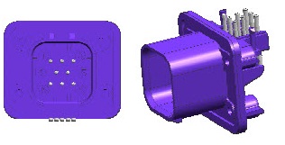
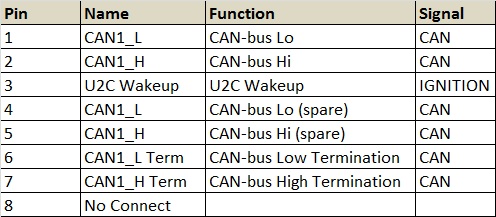
Pin 6 and 7 are only connected to CAN termination resistor (120ohms). These pins are not connected to the CAN transceiver. Pin 1 and 2 as well as 4 and 5 are connected directly to the CANL and CANH of the transciever.
High Voltage Connector
HV Connector Change
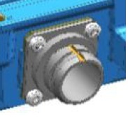
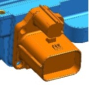
As shown in the above figure, the circular HV connector has been changed to a square connector recently. The following are notes about the changes:
- Delphi's current HV connecter from Amphenol was selected by previous customers due to its use in other areas of their vehicle.
- Delphi-Packard (PED) has an existing HV header and mating connection system that has been applied by modifying the plastic body of the header. (ONLY)
- A small modification is required to the converter housing to accommodate the PED header connecter.
- The mating connecters are currently available from Packard
HVIL Connector The HVIL connector (High voltage Interlock Loop) is a simply a shunt and is a low current signal to the battery pack. The use of HVIL in most of our customer application is to use the circuit to signal the high voltage battery pack when to discharge for safe operation. When the battery pack sees the HVIL circuit open it opens the contactors that supply voltage out, and discharges the high voltage circuit. You will notice that the connectors are interlocked in such a way that you must first remove the HVIL connector before you can remove the high voltage connector from the Converter. Since the HVIL circuit is literally a shunt in the plastic connector body and does not connect to the circuit board of the Converter, it has no function impact inside the inverter. The circuit was purely designed to be a signal to the battery pack to turn off high voltage. This is primarily a service safety feature.
- Part Number for the Converter assembly with PED is: 28304007-01
General Specs
- Rated current - 12.7 A/15 A
- Voltage Level - 450 V (DC)
- Temperature Range - -40 deg C to +110 deg C
Contents of ASM-UNIV-HV-001
The connector kit provided by New Eagle would contain the LV connector, latest HV connector, ground lugs and ring terminal. Cable assembly is not a part of connector kit.
Serial Number and Date Code Information
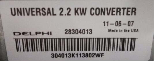
The date code for the delphi DC-DC converter follows the YY-MM-DD format and signifies when the unit was built. In the example above, the unit would have been built on June 7, 2011.
The serial number is a unique number to a unit that will not be duplicated. In the example above, the unit's serial number is 304013K113802WF.
Restrictions of Sale
This product may not be sold for use in any parallel hybrid; wheeled or tracked vehicles, including Military Vehicles, either on- or off-highway with a gross vehicle weight rating greater than 9,000 lbs, anywhere in the world, that has both an internal combustion engine and an automatic transmission. NOTE: an “automated” manual transmission is considered an automatic transmission. This restriction does not apply to vehicles that;
- do not have no transmission,
- do have a manual transmission,
- do not have an internal combustion engine (are full electric).
- are Series Hybrid implementations
Warranty
New Eagle passes through the Delphi standard Warranty – Factory Warranty All products sold by Seller under a Factory Warranty are warranted to conform to Seller’s drawings and specifications and to be free from defects in material and workmanship under normal use and service for the time period the products are at Buyer’s factory, but in no case longer than six (6) months from the date of delivery of the product to Buyer. Seller’s sole obligation, and Buyer’s exclusive remedy, under this warranty is for Seller to repair or replace or refund Buyer’s purchase price for any part of the product which fails to meet the foregoing warranty. At Seller’s option, Buyer shall return to a Seller plant location designated by Seller during the six (6) month period any product for which a claim is made, at Seller’s cost, with a written explanation of any claimed failure. Any such returns require prior authorization by Seller.
