MotoHawk Hardware
MotoHawk (formerly called MotoTron) Line of Controllers and Specifications
Please visit the following MotoHawk ECU Summary Page for MotoHawk controller family availability. This is a good starting point to help select a family for which numerous part numbers can be found by searching the data sheets in the download section (login required, can be requested by emailing sales [at] neweagle.net).
Controllers in development are also found in the download section of our site.
RoHS and MotoTron ECU Modules
Motorola had been pushing for RoHS compliance across the company since they are mainly consumer products, but when Conti took over there is no longer this push. There is no plan to go lead-free on solder for Visteon or Conti. The impact to the part design (higher reflow temps) and manufacturing is too great.
Controller Quality Certification
Both Visteon and Continental built MotoHawk modules (24, 48, 80, 128 pin modules) have QS-9000/TS16949 quality certification.
Do MotoHawk ECUs meet J1455 Heavy Duty Truck Standards?
In general, J1455 is a guideline, not really a standard. A potential OEM customer has to provide specific details on some tests called out in J1455. For vibration, some profiles are provided in the standard but the OEM has to determine the acceleration factors and duration based upon their expected system usage.
MotoHawk ECUs including the ECM24, GCM24, GCM48, ECM48 have been used in heavy duty truck applications for CAN gateways and Diesel emissions controls. In many cases, a customer will request and pay for additional testing than what was done in the validation of a MotoHawk module at either Continental or Visteon.
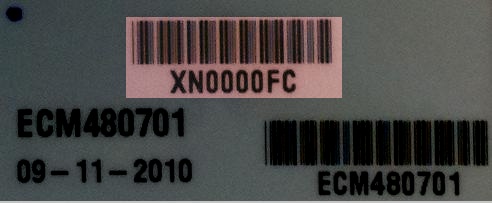
Which label contains the serial number?
Here is a label applied by Woodward that has the serial number
Specific Controller Information
HCM-563-48
What is the difference between the I/O of the model 0801 and 0803
From the data sheet, the inputs differ on the pull up to power and pull down to ground resistor values.
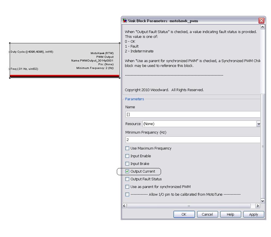
How do I access current feedback in this module?
If you double click on PWM block, and select the 'Output Current' checkbox from the list, it will give you a current in mA as an output. The following picture illustrates it.
Datasheets
Purchase
GCM-563-048
GCM-563-048-0801 (CCM48) Notes
- Note 1. The ANxM_DGxM pins may be configured as both analog and digital inputs at the same time; the intent is to allow the analog channel to be used for diagnostics of the digital channel. For these shared inputs, the DGxM time constant is 5.1 microseconds.
- Note 2. The 2.585k pull-down analog inputs have a 3k ohm pulldown in parallel with a 16.5k / 2.21k ohm voltage divider pulldown, with the Analog-Digital Converter such that:
- ADC_counts = ( 1024 / 5.00 ) * ( 2.21 / ( 2.21 + 16.50 ) ) * ( V_pin )
- or, 0 <= ADC_counts <= 1023 counts :: 0 <= V_pin <= 42.29 volts
- ADC_counts = ( 1024 / 5.00 ) * ( 2.21 / ( 2.21 + 16.50 ) ) * ( V_pin )
- Note 3. Relationship between ECUP Analog-Digital Converter counts and KEYSW voltage for GCM-0563-048-08xx and HCM-0563-048-08xx:
- ADC_counts_ECUP = ( 1024 / 5.00 ) * ( 2.21 / ( 2.21 + 16.50 ) ) * ( V_keysw - 0.7 volts )
- Please note that the default Main Power Relay block setting of 100 ADC counts corresponds to approximately KEYSW = 4.8 Vdc.
GCM-563-048 Datasheet (36303) Errata
- Page 5 calls out DRVP as pin A23, which shows up as LSO7 in pages 4, 6 and 10
- Page 5 assigns Pin A15 to STOP whereas other pages assign B23 to STOP and A15 to AN13M/DG5M
- CAN1- appears to have quite a few redundant pins – A11, B11 and B21 (Pages 9 & 10)
Current Sense Capability for GCM-563-048
- The GCM-0563-048-0801 (CCM48) module has current sense on H1+ (high side only).
- The GCM-0563-048-0802 (SIM48) module does NOT have current sense (either side).
What is a Fire48 Controller
This is an engineering acronym for the GCM48 and HCM48 families.
Purchase GCM-0563-048
- Purchase GCM-0563-048-0801-CP0-M
- Purchase GCM-0563-048-0802-CP0-M
- Purchase GCM-0563-048-0801-F-M
- Purchase GCM-0563-048-0802-F-M
ECM-563-048
The wiki page on Engine Control Modules has more information on the ECM563-48.
ECM-0555-048
The wiki page on Engine Control Modules has more information on the ECM-555-48.
ECM 555-80
The wiki page on Engine Control Modules has more information on the ECM555-80.
ECM-5554-112
For information on the ECM-5554-112, see Engine Control Modules.
ECM-565-128
The wiki page on Engine Control Modules has more information on the ECM565-128.
ECM/GCM S12-24 Controllers
For information specific to the 24pin ECMs (the SECM family) please see Engine Control Modules.
Current Draw on the 24 pin family
Power draw should be the base below, plus power required for sensor inputs (from XDRP) and driven loads.
SECM08xx (PROD): approx. 100 mA at 13.8 V (key on, module-only, no external loads or sensors). SECM08xx (DEV) : approx. 270 mA at 13.8 V (key on, module-only, no external loads or sensors). MCHI04xx (PROD): approx. 100 mA at 13.8 V (key on, module-only, no external loads or sensors). MCHI04xx (DEV) : no such animal.
The above numbers are from a quick test here on-bench for the various modules, with a baseline "empty" application and with nothing but power, ground, and CAN connections. The SECM08xx (DEV) draws additional current, to drive the additional calibratible memory circuitry. This data comes from one SECM 24-pin DEV module.
For the MCHI04xx family, the key-off fully-shutdown power draw on BATT should be less than 0.5 mA.
Difference between ECM0502 and GCM0402
When the controllers shutdown, there is a difference in the way calibrations are stored. ECM does not have separate KeySw and Battery pins so there is no way the controller would know to save the calibrations before a shutdown. In this case, it would have to save these values periodically. Whereas in case of a GCM, there are two separate KeySw and Battery pins so the module can save Non Volatile data when a shutdown is commanded and then go to sleep.
Purchase ECM-S12-024
- Purchase ECM-0S12-024-0801-CP0
- Purchase ECM-0S12-024-0801-F00
- Purchase ECM-0S12-024-0802-CPO-M
- Purchase ECM-0S12-024-0802-F00M
- Purchase ECM-0S12-024-0804-CP0-M
Purchase GCM-S12-024
Purchase 24 Pin Connector Kit
Purchase ASM-CON-004 / 24 PIN CONNECTOR KIT - ECMS12-24, GCM565-24
Purchase ASM-CON-006 / 24 PIN CONNECTOR KIT - GCMS12-24
Future MotoHawk Controllers
The MotoHawk (MotoTron) family of controllers is growing and expanding. New functions and replacement plans can be found in the download section.
ECM-OH (ECM 565-128 Replacement)
The ECM-OH is in general the replacement to the ECM565-128. It will not have the exact I/O, so refer to the datasheet and talk about your application with the sales team.
The ECM-OH is a MotoHawk programmable engine management system controller for on-highway applications.
The module is capable of full authority digital engine control (FADEC) consisting of fuel, spark, and air delivery to the engine. Additional inputs and outputs are available to control other system functions, as defined by software. This unit provides 112 connector pins with inputs, outputs, and communications interfaces that support a wide variety of applications.
The ECM-OH is part of the MotoTron Control Solutions ControlCore® family of embedded control systems. The ControlCore operating system, MotoHawk® code generation product, and MotoHawk’s suite of development tools enable rapid development of complex control systems.
Each controller is available in ‘F’ (Flash) or ‘C’ (Calibratible) versions. Flash modules are typically used for production purposes. Calibratible modules are typically for prototyping/development only; they can be calibrated in real time using MotoTune® or ToolKit.
Watchdog Function
The ECM-OH will have an ETC monitoring microprocessor and the main power supply will have a HW watchdog that needs to be tickled by the main core processor
Datasheet
General Hardware / Wiring Questions
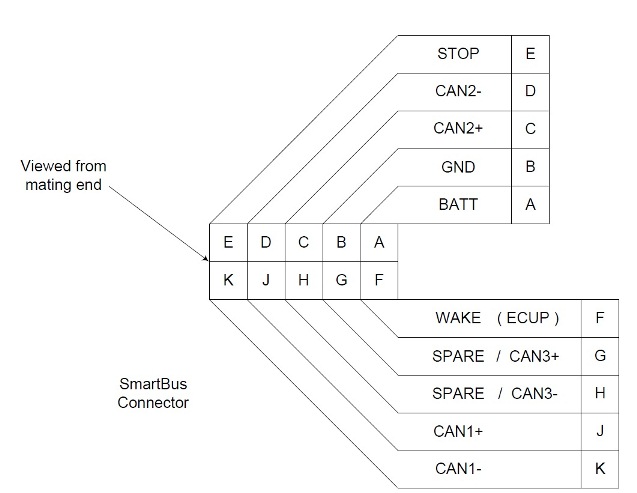
SmartCraft Pinout
Boot Key Recovery
When working in the prototype phase with newly created .srz files from MotoHawk, it is possible to program a .srz with errors in the CAN software or in the model that prevent communications with the module once programmed. When this happens, the module appears to be locked up or frozen when accessing the module via MotoTune. In this case, use the Boot Key to force the module into reboot mode such that a known, valid .srz can be reprogrammed into the module.
Understanding the Boot Key functionality
The Boot Key has a 10 pin CAN connector that should be inserted into an open port on the CAN junction box. The device generates a 555 Hz, 5V signal out of pin E when power is applied to pin A and ground applied to pin B.
At power-on, the hardboot loader for the module first looks to see if the boot key input or boot cable sequence is present. If so, the code prepares to accept programming. If no programming instructions are received from Mototune within a few seconds (~3) then the existing program application is started & recovery is not successful. At power-on (Batt and Keysw), if the hardboot loader does not detect the bootkey signal (or boot harness sequence), then the hardboot loader skips the 3-second wait and starts the existing application. So, the ECU must see the boot key signal immediately when it powers up. It can help to energize the boot key before the module (may need to disconnect the connector between ECU and the junction box, but leave power to junction box)
The recovery procedure is as follows:
1. Plug the Boot Key into the junction box and make sure that power and ground are connected to pins A and B on the junction box. Connect pin E of the junction box to the channel listed below on the following modules.
- ECM-555-48 – ESTOP
- To purchase a Boot Cable, please visit HARN-ECM-012
- ECM-555-80 – ESTOP
- PCM-565-128 – DG1
- HCM-563-48 – STOP*
- GCM-563-48 – STOP*
- If the Boot Key fails to work with above two GCM/HCM 563-48 modules, refer to Fire48 Hardboot Recovery. In order to purchase a boot cable, visit HARN-ECM-022
- ECM-5554-112 – STOP
- HCS-12 (24 pin modules) - Refer to HCS12 Boot Connections
- ECM-563-48 – N/A
- There are two approaches to doing this:
- 1.Use a Boot Cable (part number HARN-ECM-013), purchase at HARN-ECM-013, Download drawing from ECM-HARN-013 Drawing
- 2.To boot strap the ECM-563-48 modules, connect the following channels and follow the steps below.
- AN1 – AN6 Pull to +5V
- AN8 Pull to GND
- AN11 & AN12 Pull to +5V
2. With the power to the module off and the boot key installed, select a known, valid .srz file to flash onto the module and program the module at 250kbps on the module's default city-ID. All modules default to city-ID PCM-1 (0x0B) with the following exceptions:
- ECM-S12 - SECM-1 (0x81) (Not applicable to ECM-S12-24-0804 which defaults to PCM-1)
- GCM-S12 - uCHI-1 (0x91)
3. When the “Looking for an ECU” prompt appears in the dialogue box, turn on power to the ECU. The module must “wake-up” with the boot key applied in order to force a reboot.
Voltage Specifications for Modules
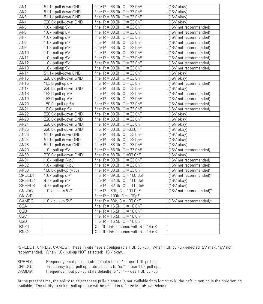
While all the modules are designed to withstand momentary short-to-battery on the input sensor pins (except those that inherently cannot be protected), the hardware validation test is typically 1 minute short-to-battery.
In the case of analog and digital inputs (nominal 5-volt), the circuit may not be able to dissipate heat when connected to a higher voltage on a longer timeframe. For instance, the pull-up or pull-down resistor may not be sized to dissipate heat from that higher voltage (resistor wattage rating).
+++++
For the circuits marked "16V okay" in the table below, the resistor wattage rating is such that continuous operation at 16V should be okay.
"Double Battery" situation: If there is a particular circuit, let me know and we can check. At nominal 24V (as high as 32V jumpstart), the trace widths as well as the PU/PD resistor may be vulnerable. Some of the pull-downs would likely be okay, but this should be verified. For example, AN4: 220k-ohm pull-down ---> P = V2 / R = 32*32 / 220e3 = 0.005 W = 5 mW. The resistor for AN4 is rated 63 mW. Depending on ambient temperature for module (heat transfer from resistor, to module body, to ambient), this circuit may be okay for short "double battery" exposure.
H-bridge Wiring
The H-bridge is normally wired as: (H+)----(load)----(H–) and the H-bridge circuit is powered from DRVP internally. (BATT)----(MPR Common, MPR Normally Open)----(DRVP)----(to H-bridge and other internal devices, and flyback diodes). The low side of the H-bridge circuitry connects to DRVGx and then back to battery ground.
ECM Differences
| MotoHawk Target | Current MotoTron part numbers (What to ask for When Ordering) | |
| ECM-0555-048-0706 | EC-0555-048-0701 (-0706 not produced, replaces -none-) | <--VR crank |
| ECM-0555-048-0707 | ECM-0555-048-0707 (-0702 no produced, Replaces -0402) | <--VR crank |
| ECM-0555-048-0708 | ECM-0555-048-0708 (-0703 not produced, replaces 0401) | <--Diital/Hall crank |
| ECM-0555-048-0709 | ECM-0555-048-0704 (0809 not produced, replaces -0401) | <--VR crank |
| ECM-0555-048-0710, | ECM-0555-048-0710 (-0705 not produced, replaces -0403) | <--VR crank (either |
| ECM-0555-048-0403 | MH target should work) | |
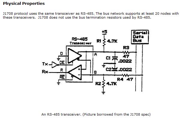
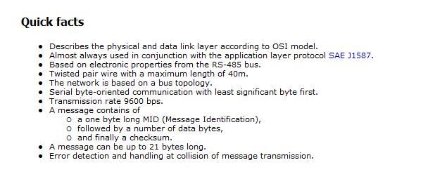
Implementing J1587 Protocol on a J1708 hardware layer (using a MotoTron RS485 Driver)
A RS485 software driver in MotoHawk can be written for J1587. The hardware signal conditioning and some general J1587 notes follow:
Communication between Serial port on ECU and USB device over RS485
Lets assume you want to use the USB with a laptop/PC and enable Mototune to communicate over RS485. So when the hardware is connected to the PC, it would be recognized by the computer, say as COM7 port.
1. Add a New Port by going to Motoserver->Ports->Add. In the window that appears, select ‘Serial’ under Type and ‘COM7’ under the Location.
2.‘Serial I/O Blocks’ in MotoHawk blockset will help define the communication over a specific protocol, RS485 in this case.
