Raptor VeeCAN
Return to the main Raptor page
Overview
The Raptor VeeCAN platform (RVC) is a Simulink toolset for development of the VeeCAN 320 Display. RVC is architected to achieve two goals. The first goal establishes the VeeCAN as a platform for the Raptor Code Generation Framework. This allows a model designed within the Raptor framework to be highly transferrable to other Raptor platforms. The second goal creates an additional framework for development of HMI (Human Machine Interface) specific features. This includes methods for graphical display and the five user action buttons.
VeeCAN Libraries
For information on the blockset libraries that support VeeCAN, Go Here
Inputs and Outputs
The following is a list of the I/O on the VeeCAN:
- (2) CAN
- (1) RS-232
- (1) Tachometer Input
- (7) Analog Inputs
- 0-10VDC
- 0-2.5VDC
- 0-500mA
- (2) Digital Inputs
- (4) Digital Outputs
CAN Development
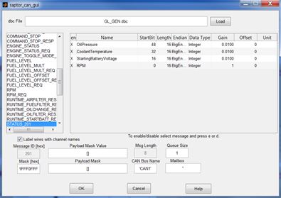
CAN development within the Raptor framework integrates industry-standard DBC files. This allows for quick sharing of a CAN protocol both within and outside the Raptor framework. The image below shows the configuration screen of a CAN Rx message block after a DBC file is selected.
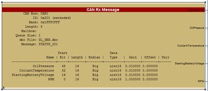
Selection of a CAN automatically populates signal output specifications on the Raptor CAN message blocks with the information contained in the DBC file, as shown in the image below.
Raptor VeeCAN Example
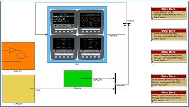
The image below is the foreground loop of a RVC project. It demonstrates separation of HMI logic from the control and signal logic This is a stylistic approach to ensure easy transferability of logic to and from other Raptor platfroms that do not have HMI functionality.
VeeCAN Display Development
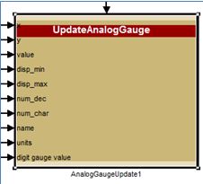
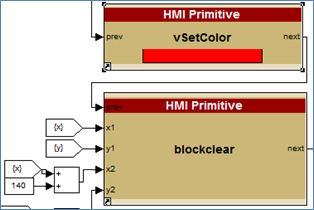
The Raptor HMI blocks were designed both to allow ease of use and to allow low-level control of display features. In the RVC library you will find high level blocks to quickly display an assortment of information and graphics, such as: lists, menus, gauges, images, and text strings. These high level blocks have been designed from a primitive block set, meaning that tweaks can be made to these under-the-covers primitives to configure the display to your taste, or to help you create your own display screens from scratch. The images below demonstrate a gauge block and a subset of the primitive blocks within it.
Simulation
The RVC simulator creates a strong link from the software development cycle to the hardware testing cycle. Typically these would be two distinct, time-consuming, phases, but, with strong coupling of the simulator and the hardware (hardware-in-the-loop simulation), and with real-time debugging, iteration time is drastically reduced.