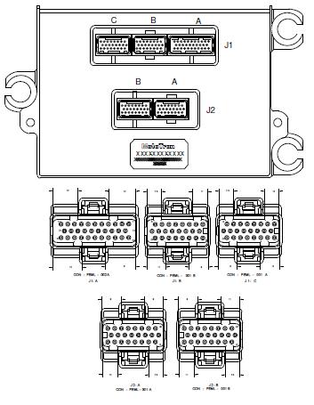
ECM-565-128
ECM-565-128
Product Summary
These controllers are capable of operating in harsh automotive, marine, and off-highway applications. The onboard floating-point unit and high clock frequency allow software to be executed in shorter times. The CAN 2.0B datalink ensures interoperability with other vehicles.
- Features include:
- Freescale MPC565, 56 MHz Microprocessor
- Operating Voltage: 9-32 VDC
- Operating temperature ranging from -40°C to 105°C
- Sealed connectors operable to 10 ft. submerged
- Family includes:
- ECM-565-128-H701-F00
- ECM-565-128-L702-C00
Datasheets
Supplementary Details to Datasheet
"ECM-565-128-0701-C_ps36320_rev01.pdf" and "ECM-0565-128-0701-F_PS_36321.pdf"
ECM-065-128-0702-CP0 is a minor rev of ECM-0565-128-0701-CP0. Same datasheet applies to both.
There are a few errata on this datasheet. To clarify:
ECM-0565-128-L701-Fxx, flash (no calibratible memory) "PROD" production module. ECM-0565-128-L70x-Cxx, calibratible "DEV" module.
Woodward part# 8237-1237 rev. NEW == ECM-0565-128-0701-F (PCM128 "PROD") Woodward part# 8237-1238 rev. A == ECM-0565-128-0702-C (PCM128 "DEV")
The PCM128 modules are nearly identical. The "PROD" -F module has 4 extra analog inputs and 4 extra digital inputs; the "DEV" -C module has 2 wide-band oxygen (lambda) sensor inputs and 2 extra knock channels, as well as additional RAM. For the 2007 model-year, these modules have three H-bridges: 10-amp continuous, 12-amp peak. (The datasheet is being updated to reflect the higher-ampacity capability of H1 and H2, due to board layout revision.)
General Comments:
The low-side fuel injector drivers INJx may be run as 3A peak / 1A hold (all 12 injector drivers), or 7A peak / 3A hold (6 drivers as indicated). Use the "Injector Current Select" block in the MotoHawk Advanced Digital I/O library to select.
The fuel injector drivers INJx and LSDx low-side drivers may be used as PWM outputs or as discrete outputs. These outputs act as a switch to ground. When the MOSFET is ON, the module resource pin is connected internally to the module DRVGx driver ground pins.
The maximum current rating for the ECU terminal pins is 10 amps continuous. However, most circuits have a lower current rating depending on the type of circuit connected inside. These ratings are shown on the ECU datasheet.
For the analog and digital input circuits, the actual current draw is dependent on the wiring connections. Generally, these are either sensor transducer inputs, or potentiometer / thermistor / RTD resistive devices forming a voltage divider with the internal pull-up or pull-down circuit.
Knock circuitry difference on the Calibration (Dev) and Flash (Prod) Units
Four of the pins can be used as DG5 to DG8 on the PROD module, and as KNK3 (2 pins) and KNK4 (2 pins) on the DEV module.
Connector Pinouts
Other Engine Control Modules
More Information: Engine Control Modules
