Sensors-and-Actuators
Voltage Specifications for Modules
While all the modules are designed to withstand momentary short-to-battery on the input sensor pins (except those that inherently cannot be protected), the hardware validation test is typically 1 minute short-to-battery.
In the case of analog and digital inputs (nominal 5-volt), the circuit may not be able to dissipate heat when connected to a higher voltage on a longer timeframe. For instance, the pull-up or pull-down resistor may not be sized to dissipate heat from that higher voltage (resistor wattage rating).
+++++
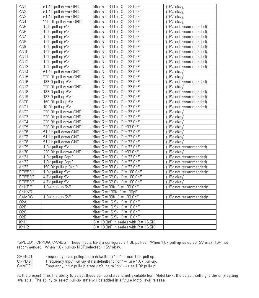
For the circuits marked "16V okay" in the table below, the resistor wattage rating is such that continuous operation at 16V should be okay.
"Double Battery" situation: If there is a particular circuit, let me know and we can check. At nominal 24V (as high as 32V jumpstart), the trace widths as well as the PU/PD resistor may be vulnerable. Some of the pull-downs would likely be okay, but this should be verified. For example, AN4: 220k-ohm pull-down ---> P = V2 / R = 32*32 / 220e3 = 0.005 W = 5 mW. The resistor for AN4 is rated 63 mW. Depending on ambient temperature for module (heat transfer from resistor, to module body, to ambient), this circuit may be okay for short "double battery" exposure.

H-bridge Wiring
The H-bridge is normally wired as: (H+)----(load)----(H–) and the H-bridge circuit is powered from DRVP internally. (BATT)----(MPR Common, MPR Normally Open)----(DRVP)----(to H-bridge and other internal devices, and flyback diodes). The low side of the H-bridge circuitry connects to DRVGx and then back to battery ground.
ECM Differences
| MotoHawk Target | Current MotoTron part numbers (What to ask for When Ordering) | |
| ECM-0555-048-0706 | EC-0555-048-0701 (-0706 not produced, replaces -none-) | <--VR crank |
| ECM-0555-048-0707 | ECM-0555-048-0707 (-0702 no produced, Replaces -0402) | <--VR crank |
| ECM-0555-048-0708 | ECM-0555-048-0708 (-0703 not produced, replaces 0401) | <--Diital/Hall crank |
| ECM-0555-048-0709 | ECM-0555-048-0704 (0809 not produced, replaces -0401) | <--VR crank |
| ECM-0555-048-0710, | ECM-0555-048-0710 (-0705 not produced, replaces -0403) | <--VR crank (either |
| ECM-0555-048-0403 | MH target should work) | |
Implementing J1587 Protocol on a J1708 hardware layer (using a MotoTron RS485 Driver)
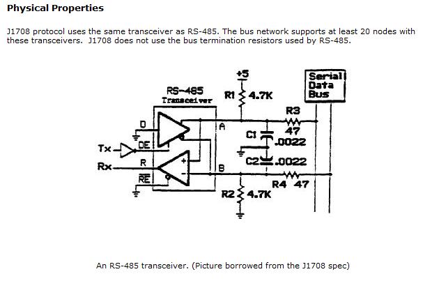
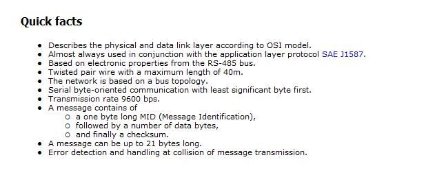
A RS485 software driver in MotoHawk can be written for J1587. The hardware signal conditioning and some general J1587 notes follow:

