VeeCAN 320: Difference between revisions
| (28 intermediate revisions by 6 users not shown) | |||
| Line 1: | Line 1: | ||
== | This product comes in two versions: a Raptor version and an SDK version. You are viewing the standard SDK version. Click '''[[Raptor_VeeCAN_320|here]]''' to see the Raptor version. | ||
===Introduction=== | |||
[[Image:VeeCAN320.JPG]] | [[Image:VeeCAN320.JPG]] | ||
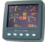
Veethree has replaced its CANvu CAN bus display with the 3.5" color VeeCAN 320. | |||
*7 analog inputs, 3 digital inputs, 4 outputs, 2 CAN connections and USB 2.0 | |||
*Optional Raptor Interface and software development kit (SDK) to allow for customization | |||
*IP67 approved | |||
*Designed for harsh operating environments | |||
*CAN ports meet CAN 2.0B and NMEA 2000 (using isolated CAN) specifications. The software is tested using NMEA 2000. | |||
*Standard product includes the Veethree Engine Monitor (VEM), a J1939 engine monitor. | |||
For | For a link to purchase, please return to the previous page '''[[Displays#VeeCAN_320|here]]'''. | ||
===VeeCAN 320 Hardware Specifications=== | ===VeeCAN 320 Hardware Specifications=== | ||
*The second CAN line is | *The second CAN line is galvanically isolated, whereas the first CAN line is not. | ||
*In order to use the secondary CAN bus (ISOLATED CAN_HI and ISOLATED CAN_LO), ISOLATED CAN SUPPLY VBATT and ISOLATED CAN SUPPLY GROUND need to be tied to battery power and ground, respectively. Please see '''[[ | *In order to use the secondary CAN bus (ISOLATED CAN_HI and ISOLATED CAN_LO), ISOLATED CAN SUPPLY VBATT and ISOLATED CAN SUPPLY GROUND need to be tied to battery power and ground, respectively. Please see the '''[[Displays#VeeCAN_320|VeeCAN 320 Datasheet]]''' for pinout. | ||
*There | *There are 128MB of non-volatile memory to run programs on the VeeCAN 320. | ||
*There is no choke inductor on the VeeCAN's CAN bus. | *There is no choke inductor on the VeeCAN's CAN bus. | ||
| Line 35: | Line 29: | ||
*The microprocessor is a Freescale i.MX 286, running at 454 MHz with 128 MB NAND and 128 MB SDRAM | *The microprocessor is a Freescale i.MX 286, running at 454 MHz with 128 MB NAND and 128 MB SDRAM | ||
*The shock and vibration specification on the VeeCAN is run to J1810, Paragraph 5.5, where the relevant information is: | |||
-------------------------------------- | |||
Subject the unit to three half sine 10±1g shocks of 12 ms±1ms duration in the vertical, lateral and the unit shall be tested for basic operation i.e. power up and serial communication is operational. After testing, the unit shall complete a full operational test and exhibit no damage. | |||
--------------------------------------- | |||
===Mounting Information=== | |||
The displays have M4 x 0.7 threads. It is recommended to use plastic studs and thumb nuts. Metal screws can be used but the length of the screw must be taken in consideration with the thickness of the panel, so the screw does not drill into the housing of the display. Over-torquing screws can penetrate into the display causing internal damage. | |||
=== | ===Downloads=== | ||
:'''[http://www.neweagle.net/support/wiki/ProductDocumentation/NonRaptorDisplays/VeeCAN320_DataSheet.pdf Datasheet]''' | |||
:'''[http://www.neweagle.net/support/wiki/ProductDocumentation/NonRaptorDisplays/VeeCAN320_UserManual.pdf User Manual]''' | |||
:'''[http://www.neweagle.net/support/wiki/ProductDocumentation/NonRaptorDisplays/VeeCAN320_3dCAD.zip 3-D CAD (.stp)]''' | |||
{ | {{VeeCAN_320_Template}} | ||
===VeeCAN Protective Push Cover=== | ===VeeCAN Protective Push Cover=== | ||
{|class="wikitable" cellpadding = "5" | {|class="wikitable" cellpadding="5" style="text-align:center;" | ||
!scope="col"|Picture | |||
!scope="col"| | !scope="col"|Part Number | ||
!scope="col"| | !scope="col"|Webstore | ||
!scope="col"| | |||
!scope="col"|Drawings | !scope="col"|Drawings | ||
|- | |- | ||
|style = "width: | |style = "width: 180px;"| | ||
<gallery> | <gallery> | ||
File:Veecan protective push cover.jpg | File:Veecan protective push cover.jpg | ||
</gallery> | </gallery> | ||
|style = "width: | |style = "width: 180px;"| | ||
[ | VeeCAN 320-CVR | ||
|style = "width: | |style = "width: 180px;"| | ||
[http://www.neweagle.net/support/wiki/images/f/f9/69449_R2.pdf VeeCAN Protective Cover Drawing] | '''[https://store.neweagle.net/shop/products/displays-gauges/display-add-ons/protective-cover-for-veecan-320-and-320l/ VeeCAN 320 Push Cover]''' | ||
|style = "width: 180px;"| | |||
'''[http://www.neweagle.net/support/wiki/images/f/f9/69449_R2.pdf VeeCAN Protective<br> Cover Drawing]''' | |||
|} | |} | ||
Latest revision as of 15:32, 23 February 2023
This product comes in two versions: a Raptor version and an SDK version. You are viewing the standard SDK version. Click here to see the Raptor version.
Introduction
Veethree has replaced its CANvu CAN bus display with the 3.5" color VeeCAN 320.
- 7 analog inputs, 3 digital inputs, 4 outputs, 2 CAN connections and USB 2.0
- Optional Raptor Interface and software development kit (SDK) to allow for customization
- IP67 approved
- Designed for harsh operating environments
- CAN ports meet CAN 2.0B and NMEA 2000 (using isolated CAN) specifications. The software is tested using NMEA 2000.
- Standard product includes the Veethree Engine Monitor (VEM), a J1939 engine monitor.
For a link to purchase, please return to the previous page here.
VeeCAN 320 Hardware Specifications
- The second CAN line is galvanically isolated, whereas the first CAN line is not.
- In order to use the secondary CAN bus (ISOLATED CAN_HI and ISOLATED CAN_LO), ISOLATED CAN SUPPLY VBATT and ISOLATED CAN SUPPLY GROUND need to be tied to battery power and ground, respectively. Please see the VeeCAN 320 Datasheet for pinout.
- There are 128MB of non-volatile memory to run programs on the VeeCAN 320.
- There is no choke inductor on the VeeCAN's CAN bus.
- The microprocessor is a Freescale i.MX 286, running at 454 MHz with 128 MB NAND and 128 MB SDRAM
- The shock and vibration specification on the VeeCAN is run to J1810, Paragraph 5.5, where the relevant information is:
Subject the unit to three half sine 10±1g shocks of 12 ms±1ms duration in the vertical, lateral and the unit shall be tested for basic operation i.e. power up and serial communication is operational. After testing, the unit shall complete a full operational test and exhibit no damage.
Mounting Information
The displays have M4 x 0.7 threads. It is recommended to use plastic studs and thumb nuts. Metal screws can be used but the length of the screw must be taken in consideration with the thickness of the panel, so the screw does not drill into the housing of the display. Over-torquing screws can penetrate into the display causing internal damage.
Downloads
VeeCAN Software SDK and Compiler
The VeeCAN 320 has an optional Software Development Kit for programming in C and a Raptor Simulink programming interface. It uses a free linux gcc compiler. Contact sales or vist the webstore for pricing and availability. Application engineering is available to help build your display or provide additional support.
Example Screens
New Eagle develops custom screens and sells a tool that allows a user to easily create their own custom screens, communications and logic on the VeeCAN 320. For more examples, click here.
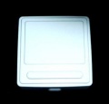
VeeCAN Protective Push Cover
| Picture | Part Number | Webstore | Drawings |
|---|---|---|---|
|
|
VeeCAN 320-CVR |


