ECM-S12X-070: Difference between revisions
| Line 40: | Line 40: | ||
'''[http://www.neweagle.net/support/wiki/docs/Harnesses/70pin/WEB372510124475404-1207_ALL_NEW.pdf ECM-S12X-070-1001 to Simulator Harness]''' | '''[http://www.neweagle.net/support/wiki/docs/Harnesses/70pin/WEB372510124475404-1207_ALL_NEW.pdf ECM-S12X-070-1001 to Simulator Harness]''' | ||
== | ===S12(X) Recommended Stack Size=== | ||
'''[[ | The [http://www.neweagle.net/support/wiki/index.php?title=MotoHawk_Resource_Documents "Working with the S12" Application Document] indicates a stack baseline when starting your application. Below is another recommended stack size if the stack baseline is low in certain areas. | ||
'''NOTE:''' The following stack sizes are recommendations and should be adjusted according to the application requirements. | |||
[[File:S12_stack.png]] | |||
==Webstore== | ==Webstore== | ||
Revision as of 13:51, 21 May 2014
ECM-S12X-070
Product Summary
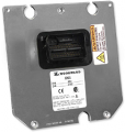
A new Engine Control Module in the MotoHawk modules product line, these rugged controllers are capable of operating in harsh automotive, marine, and off-highway applications. Numerous marine applications have proven the capability of this family. Based on the Freescale MC9S12 family of microprocessors, the ECM-S12X-070-1001 is capable of delivering complex control strategies. The onboard floating-point unit and high clock frequency allow software to be executed in shorter times. The CAN 2.0B datalink ensures interoperability with other vehicle systems.
- Features include:
- Freescale MC9S12XET256, 50 MHz Microprocessor
- Operating Voltage: 6.5-16 V, 24V (Jump start), 5V (crank)
- Operating Temperature: -40deg C to +85deg C (105deg C in some applications)
Datasheets
LSD Information
- Only LSO1 has current sensing. The current monitoring on LSO1 is intended for diagnostic purposes, or to indicate high vs. low motor load. The Vad=.255*lout, and is 10-bit.
- PWM is supported in MotoHawk on LSO1, 2, 3, 4, 5, 6, 7, and 8. However, only LSO 2, 3, and 4 have a flyback diode and are intended to be used as PWM. They are intended to be used as a discrete output, unless the load has no stored energy.
- For the LSO1 is capable capable of PWM, however the flyback diode is not sized for continuous PWM and was intended for discrete mode.
- If you look at the datasheet for LSO1 it will mention an A, B, and C pin. These are not separate LSO's, but instead all three pins are parallel outputs for LSO1 to allow for a higher current output.
- Family includes:
- ECM-S12X-070-1001
Quiescent Current
Measured quiescent current @ 12V = 131 mA, no loads
CAN bus limitations
The S12 modules do not support 1000kbaud CAN bus speeds; they are hardware limited.
Harness Drawings
ECM-S12X-070-1001 Pigtail Harness
ECM-S12X-070-1001 Programming Harness
ECM-S12X-070-1001 to Simulator Harness
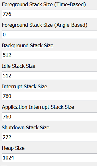
S12(X) Recommended Stack Size
The "Working with the S12" Application Document indicates a stack baseline when starting your application. Below is another recommended stack size if the stack baseline is low in certain areas.
NOTE: The following stack sizes are recommendations and should be adjusted according to the application requirements.

