ECM-S12X-070
ECM-S12X-070
Product Summary
A new Engine Control Module in the MotoHawk modules product line, these rugged controllers are capable of operating in harsh automotive, marine and off-highway applications. Numerous marine applications have proven the capability of this family. Based on the Freescale MC9S12 family of microprocessors, the ECM-S12X-070-1001 is capable of delivering complex control strategies. The onboard floating-point unit and high clock frequency allow software to be executed in shorter times. The CAN 2.0B datalink ensures interoperability with other vehicle systems.
Features include:
- Freescale MC9S12XET256, 50 MHz Microprocessor
- Operating voltage: 6.5-16V, 24V (Jump start), 5V (crank)
- Operating temperature: -40°C to +85°C (105°C in some applications)
Family includes:
- ECM-S12X-070-1001
Datasheets
ECM-S12X-70-1001
LSD Information
- Only LSO1 has current sensing. The current monitoring on LSO1 is intended for diagnostic purposes, or to indicate high vs. low motor load. The Vad=0.255*lout and is 10-bit.
- PWM is supported in MotoHawk on LSO1, 2, 3, 4, 5, 6, 7 and 8. However, only LSO 2, 3 and 4 have a flyback diode and are intended to be used as PWM. They are intended to be used as a discrete output, unless the load has no stored energy.
- For the LSO1 is capable of PWM, however the flyback diode is not sized for continuous PWM and was intended for discrete mode.
- If you look at the datasheet for LSO1 it will mention A, B and C pins. These are not separate LSOs, but instead all three pins are parallel outputs for LSO1 to allow for a higher current output.
Quiescent Current
Measured quiescent current at 12V = 131 mA, no loads.
CAN Bus Limitations
The S12 modules do not support 1000 kbaud CAN bus speeds; they are hardware limited.
Harness Drawings
ECM-S12X-070-1001
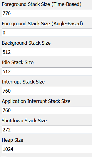
S12X Recommended Stack Size
The Working with the S12 application document indicates a stack baseline when starting your application. Below is another recommended stack size if the stack baseline is low in certain areas.
Note: The following stack sizes are recommendations and should be adjusted according to the application requirements.
Troubleshooting
Out of Allocation Space
If you are getting an error message:
L1102: out of allocation space in segment PAGE_E0_SEG at address 0xE08A0C
The issue is due to the way the flash pages are written on this module. Adjusting the stack size in the target definition block will not address the issue, the stack settings in the target definition block affect the RAM allocation, the problem is related to FLASH allocation.
To correct:
- Remove any unnecessary blocks/subsystems from your model.
- Since this ECU uses paged FLASH, you may be able to restructure your model to have more top level triggers (such as multiple foreground triggered subsystems) so that your tasks can be allocated to the FLASH pages differently so as not to cause an allocation error with a particular page.
