MotoTune-FAQ
Connection Troubleshooting
The following should be checked if you have encountered communication problems with the controller.
- 1. With key-on, check for power at ECUP (pin F on the J-Box) and BATT, if applicable (pin A on the J-Box).
- 2. Check continuity between battery ground, the J-box ground and the ECU ground.
- 3. Check for the correct polarity on CAN wires. Pin J is CAN+ and pin K is CAN-.
- 4. Check for the appropriate port set-up under the Moto-Server icon.
- 5. If all of the above are set correctly, reset the Moto-Server by right-clicking on the satellite from the task bar and exiting. Close MotoTune, unplug the Kavaser USB connector from the CAN/USB hub and computer.
- 6. Restart MotoTune and plug the Kavaser USB back into the computer and the CAN/USB hub.
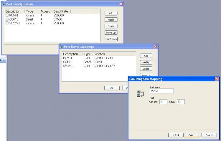
Adding a Port and setting the CityID
Communication problems can also arise when trying to communicate with two different controllers simultaneously. MotoTune uses an identifier called a CityID to identify the hardware online. In the model, the city ID is set under in the 'CAN ID' block.
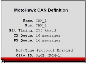
Follow these steps to add a new port location with a unique CityID:
- 1. Right click on the MotoServer Satellite icon on the task bar, right click on Ports.
- 2. The Ports Configuration will pop up and then click on 'Edit Names'.
- 3. A new window pops up labeled 'Port Name Mappings'. :4. Click on 'Add' and choose 'CAN Kingdom' and hit Next.
- 5. Give the new location a name (PCM-2 or PCM-B) and set the CityID. *Note: (Hex A == Dec 10, Hex B == Dec 11, Hex C == Dec 12, Hex D == Dec 13)
Boot Key Recovery
When working in the prototype phase with newly created .srz files from MotoHawk, it possible to program an .srz with errors in the CAN software or in the model that prevent communications with the module once programmed. When this happens, the module appears to be locked up or frozen when accessing the module via MotoTune. In this case, use the Boot Key to force the module into reboot mode such that a known, valid .srz can be reprogrammed into the module.
The Boot Key has a 10 pin CAN connector that should be inserted into an open port on the CAN junction box. The device generates a 555 Hz, 5V signal out of pin E when power is applied to pin A and ground applied to pin B. When this signal is received on the appropriate pin of the module, it is forced into reboot mode and will allow the module to be reprogrammed.
1. Plug the Boot Key into the junction box and make sure that power and ground are connected to pins A and B on the junction box. Connect pin E of the junction box to the channel listed below on the following modules.
- ECM48_555 – ESTOP
- PCM80_555 – ESTOP
- PCM128_565 – DG1
- HCM48_563 - STOP
- ECM112_5554 - STOP
- ECM48_563 – N/A
- To boot strap the ECM48_563 module, connector the following channels and follow the steps below.
- AN1 – AN6 Pull to +5V
- AN8 Pull to GND
- AN11 & AN12 Pull to +5V
- 24 Pin S12 modules use the HCS12 Boot Cable
2. With the power to the module off and the boot key installed, select a known, valid .srz file to flash onto the module and program the module.
3. When the “Looking for an ECU” prompt appears in the dialogue box, turn on power to the ECU. The module must “wake-up” with the boot key applied in order to force a reboot.
Programming Procedures
Basic Programming Procedure
1. During the MotoTune installation, an ECU Files folder is created on the C: drive of the computer, with the following folders:
- Cals for calibration (.cal) files
- Diaplays for display (.dis) files
- Programs for program (.srz) files
- TBDLL for the dynamic link library (.dll) files
3. Smart Craft Hub Voltage Check
Make sure that the termination block is connected to the hub and that the ECU is connected via the 10-pin connector to the smart craft hub. With power ON from the battery and the key switch enabled, check the following readings on the hub.
- Make sure that +12 is read across pins A and B
- Check for +12 across pins F and B with key switch enabled
- Check resistance across pins J and K (should be 120 Ohms if termination block is connected)
3. MotoTune Procedure
You will need to have a program file generated from Matlab to program.
- Open MotoTune
- Turn off all external power
- Make sure that the port setting is set to PCM1 at 250kbaud.
- Hit Program
- Turn on external power and then key switch
TRANSFER-UPGRADE and SYNCHRONIZE
Please note that if the dimensions of an array or map have changed, Transfer-Upgrade will need help in moving the table from one build .CAL file to the next. Transfer-Upgrade moves values from one .CAL file into another, by the VARDEC name only. If the VARDEC's attributes (dimensions, etc.) have changed, or the VARDEC is new or has been deleted, that info is shown as well.
The normal process for moving from one software build to the next (e.g. from MyApp_002.srz to MyApp_003.srz) is:
- 1. Download calibration (desired settings) from module running old program, creating: MyApp_002_(description).cal
- 2. Create a template calibration file, either "from programming file" or by downloading from module running new program: MyApp_003_template.cal
- 3. Do a Transfer-Upgrade from MyApp_002_(description).cal into MyApp_003_template.cal, which copies, by VARDEC name, settings from the source .CAL into the destination .CAL. You get a chance to save into a new file: MyApp_003_(description).cal. The destination template tells MotoTune what settings exist to be transferred.
- 4. After programming an ECU module with the new program, open the upgraded calibration file MyApp_003_(description).cal in MotoTune. Go on-line (if opened off-line), right-click the calibration filename, and select "Synchronize" to synch disk (file) contents with ECU contents.
- PLEASE NOTE: if there are calibration file settings that are stored in FLASH memory (instead of EEPROM non-volatile memory), those will cause an error message about not being able to change and asking if ECU is a production FLASH module. If you are trying to change settings stored in FLASH (typical calibration setting not set as Volatile or NonVolatile memory storage), then you will need to MERGE the upgraded calibration file back into the new .SRZ program, and then re-flash the ECU module with the new, transfer-upgraded calibration.
MERGE and Re-flash
- 1. Take the MyApp_003_(description).cal file and the MyApp_003.srz file. Use File-->Merge, or the Merge button, or (when calibration file is open, off-line) right-click on calibration filename and choose Merge.
- 2. Merge the calibration file into the .SRZ file. This will make the calibration settings in the .CAL file become the factory default settings in the .SRZ file. Save the resulting file: MyApp_003_(description).srz
- 3. Program the ECU module with MyApp_003_(description).srz
Installation Procedure
To install MT/MSR 8.13.7.118, the MotoTune developer team recommends:
- 1. Exit all open MotoTune (and MATLAB / MotoHawk) sessions.
- 2. Using Windows Task Manager, check for any "mnfeature.exe" processes running; if so, kill with "End Process".
- 3. Using Windows Add / Remove Programs, uninstall: MotoTune
- 4. Using Windows Add / Remove Programs, uninstall: MotoServerRuntime
- 5. Delete folder "C:\Program Files\Common Files\MotoTron\Server\" (this deletes files "mnfeature.exe" and "mnfeatureps.dll")
- 6. Unzip the contents of the respective new installer zipfiles into a temporary directory. (MotoServerRuntime now has a helper folder "ISSetupPrerequisites" that must be in the same folder as the installer .EXE file when you run it.)
- 7. Install: MotoServerRuntime (as administrator, on Windows Vista machines)
- 8. Install: MotoTune (as administrator, on Windows Vista machines)
Licensing
You can use the MotoTron License Viewer (Start, All Programs, MotoTools, MotoTron License Viewer) to check licensing in your token.
To update your token, please send the token serial number and license transaction file to: license@neweagle.net
To see serial number information (requires MotoServerRuntime 8.13.6.73 or later).
- 1. Start MotoTune (to start MotoServerRuntime (antenna dish in lower right corner).
- 2. Right-click antenna dish, choose "About MotoServer"
- 3. Choose "License Info"
- 4. Choose "Token Info" (this info may be CTRL-V pasted into an email)
Use LicenseUpdate (Start, All Programs, MotoTools, LicenseUpdate) to create transaction file.
Additional information is on the Woodward MotoTron Control Solutions wiki page: http://mcs.woodward.com/support/wiki/index.php?title=License_Update
Configuring Default Path
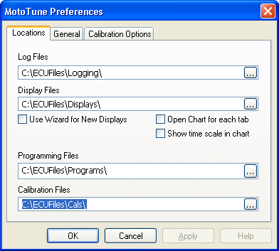
MotoHawk uses the same locations set by MotoTune. These can be changed by accessing you MotoTune preferences File->Preferences
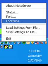
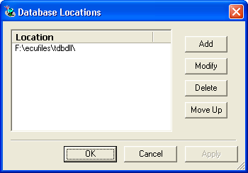
To setup the DLL directory, follow the steps shown in the pictures below:
To check if the paths are setup correctly, you can run the following commands at the MATLAB command prompt :
      >> motohawk_tools_directory(0, 'SRZ')

      ans =

      F:\ECUFiles\Programs\

      >> motohawk_tools_directory(0, 'DLL')

      ans =

      F:\ecufiles\tdbdll\

      >>
You should see something like this near the end of the build:
     ### Installing .srz in F:\ECUFiles\Programs\, and .dll in F:\ecufiles\tdbdll\

     f:\data\scratch\nsistest\nsistest_Build>copy .\Target\nsistest_003_DEV.srz F:\ECUFiles\Programs\\nsistest_003.srz
       1 file(s) copied.
     ### Created Development Executable: nsistest_003.srz

     f:\data\scratch\nsistest\nsistest_Build>copy .\TDB\nsistest_003.dll F:\ecufiles\tdbdll\\nsistest_003.dll
       1 file(s) copied.

     ### Created MotoTune DLL: nsistest_003.dll
