MotoTune-FAQ
New Eagle > Products Wiki > MotoHawk Platform > MotoTune > MotoTune FAQ
What are the minimum PC system requirements for MotoTune?
The official requirements are stated as:
- Pentium® III 667 MHz PC
- 256 MB of RAM
- Windows XP SP2 and Vista or greater
- MotoServerRuntime is a prerequisite
MotoTune 8.13.7.120 has been used successfully on Windows 7 x64 as well. Based on past working experience, MotoTune 8.13.7.120 has proven to be a relatively more stable version than 8.13.7.140.
Windows OS Compatibility
MotoTune is compatible with the 32- and 64-bit versions of Windows XP, Windows 7, Windows 8 and Windows 10.
MotoTune Dongle and USB 3.0 Compatibility
The MotoTune dongle is not plug-and-play compatible with USB 3.0. There is a workaround in place: by changing the BIOS settings on the computer, the dongle will be installed.
Dongle and USB 3.0 Workaround
This problem is caused by an error in the Windows 7 driver of the USB 3.0 controller which does not treat some USB commands correctly according to the USB specifications.
However, independent from updates from Intel, we are currently testing a new driver version for the CRYPTO-BOX with a workaround for this USB 3.0 problem. If you want to test this driver, please download it here: www.marx.com/ftp/temp/USB3/CBU_Test_Drv_21Jan2013.zip
IMPORTANT: The driver should work fine but is currently not yet digitally signed! To install it under Windows 7 64-bit versions, you have to restart the computer and hit the F8 key multiple times before Windows starts. Then choose "Disable Driver Signature Enforcement". This has to be done each time Windows starts when using this driver. We will offer a WHQL certified version of the driver as soon as we have finished testing and passed certification procedure. Make sure that you have plugged in the CRYPTO-BOX. Unzip the driver package. Open the Device Manager, right-click on the "CBUSB ver 2.0" device and choose "Update Driver Software" -> "Browse my computer for driver software" -> "Let me pick from a list of device drivers on my computer" -> "Have Disk". Now select the corresponding 32- or 64-bit .INF file from the driver package and click "OK". If Windows says that the driver is not signed, choose that you want to install the driver anyway.
Another USB 3.0 Workaround
Turn off the xHCI mode in your computer's BIOS settings. This will cause the super-speed of the USB 3.0 interface to throttle down to high-speed (USB 2.0); in our tests it ran perfectly. Most motherboards allow to disable the xHCI mode in the BIOS selectively to individual USB 3.0 ports, so you can still use the other ports at full speed.
MotoTools Version FAQs
MotoTools does not support multiple versions installed simultaneously. For all MotoTools (MotoUpdate, MotoViewer, MotoTune and MotoServerRuntime) the user should have only one version installed. It is recommended to use Windows Add/Remove programs to uninstall the older version before starting a new installation. Also, the versions of MotoTune, MotoService and MotoServerRuntime must be the same.
Installation Procedure
The following installation procedure is recommended for installing MotoServerRuntime and MotoTune:
- Exit all open MotoTune (and MATLAB/MotoHawk) sessions.
- Using Windows Task Manager, check for any "mnfeature.exe" processes running; if so, kill with "End Process".
- Using Windows Add/Remove Programs, uninstall MotoTune
- Using Windows Add/Remove Programs, uninstall MotoServerRuntime
- Delete folder "C:\Program Files\Common Files\MotoTron\Server\" (This deletes files "mnfeature.exe" and "mnfeatureps.dll")
- Unzip the contents of the respective new installer zip files into a temporary directory.
(MotoServerRuntime now has a helper folder "ISSetupPrerequisites" that must be in the same folder as the installer .exe file when you run it.) - Install MotoServerRuntime (as administrator on Windows Vista and 7 machines)
- Install MotoTune (as administrator on Windows Vista and 7 machines)
MotoTune Basics
- Introduction to MotoTune and Programming Process
- Creating and Working with Displays
- Charting and Logging Data in Displays
- Creating a Calibration and Making Real Time Calibration Changes
Baud Rate
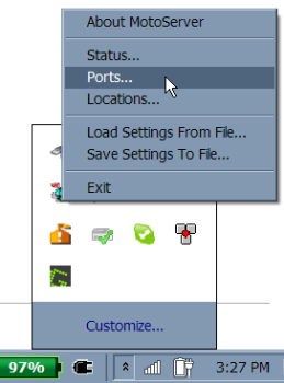
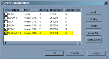
The default value for the baud rate for PCM-1 is 250K, which is also the default value when the boot key is used. So, when you program the module for a baud rate of 125K and a port is not set up to receive that value, MotoTune cannot connect. Create a new port or modify the existing one to fix this problem. To do this, open MotoTune and then right click on the satellite dish icon in the bottom right of the window page in the start program. Open the bar and then left click on Ports. There you can modify the baud rate of an existing port or create a new port. When the boot key is plugged in, the module automatically goes to 250K, allowing you to program. If you want to check and see if a device/ECU is on the bus but you don’t know the city ID or the baud rate, try the MotoHawk scanner. The MotoHawk scanner goes through common baud rates and lists all devices on the bus by city ID and baud rate. It also says whether a Kvaser device is detected. Close all other programs that might use the bus, such as MotoTune and CANKing, when using the scanner.
Configuring Default Path
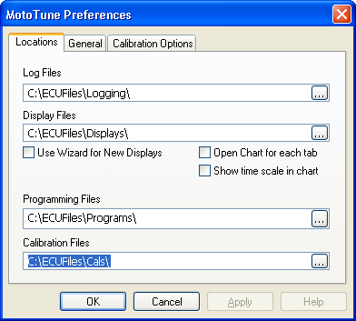
MotoHawk uses the same locations set by MotoTune. These can be changed by accessing MotoTune preferences. This can be done by clicking File -> Preferences
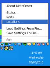
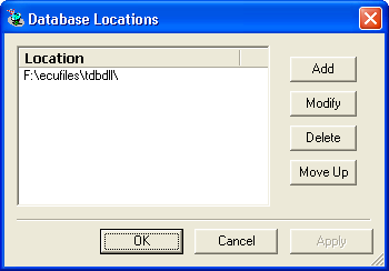
To setup the DLL directory, follow the steps shown in the pictures below:
To check if the paths are setup correctly, you can run the following commands at the MATLAB command prompt:
      >> motohawk_tools_directory(0, 'SRZ')

      ans =

      F:\ECUFiles\Programs\

      >> motohawk_tools_directory(0, 'DLL')

      ans =

      F:\ecufiles\tdbdll\

      >>
You should see something like this near the end of the build:
     ### Installing .srz in F:\ECUFiles\Programs\, and .dll in F:\ecufiles\tdbdll\

     f:\data\scratch\nsistest\nsistest_Build>copy .\Target\nsistest_003_DEV.srz F:\ECUFiles\Programs\\nsistest_003.srz
       1 file(s) copied.
     ### Created Development Executable: nsistest_003.srz

     f:\data\scratch\nsistest\nsistest_Build>copy .\TDB\nsistest_003.dll F:\ecufiles\tdbdll\\nsistest_003.dll
       1 file(s) copied.

     ### Created MotoTune DLL: nsistest_003.dll
Which version of MotoTune goes with a specific MotoHawk version?
In general, versions of MotoTune are not dependent on MotoHawk (excluding MotoHawk 2011a, which requires MotoTune version 8.13.7.145 or later).
Licensing
You can use the MotoTron License Viewer (Start -> All Programs -> MotoTools -> MotoTron License Viewer) to check the licensing in your token. To update your token, please send the token serial number and license transaction file to licenses@neweagle.net
Click here to learn how to find the serial number.
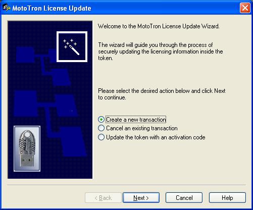
License Updating Procedure
Start -> All Programs -> MotoTools -> LicenseUpdate -> Create a New Transaction
Programming Procedures
Basic Programming Procedure
1. During the MotoTune installation, an ECUFiles folder is created on the C: drive of the computer, with the following folders:
- Cals for calibration (.cal) files
- Displays for display (.dis) files
- Programs for program (.srz) files
- TDBDLL for the dynamic link library (.dll) files
2. SmartCraft Hub Voltage Check
Make sure that the termination block is connected to the hub and that the ECU is connected via the 10-pin connector to the SmartCraft hub. With power ON from the battery and the key-switch enabled, check the following readings on the hub:
- Make sure that +12 is read across pins A and B.
- Check for +12 across pins F and B with the key-switch enabled.
- Check resistance across pins J and K (should be 120Ω if termination block is connected).
3. MotoTune Procedure
You will need to have a program file compiled to program. This is the *.srz file that is generated after a successful build. The file is located in the Programs folder.
- Open MotoTune.
- Turn off all external power.
- Make sure that the port setting is set to the correct baud rate and city ID that was last flashed/programmed onto the module. (Please note that the port should be set to PCM1/250K baud for a module brand new out of the package).
- Hit Program.
- Turn on external power and then the key-switch.
Troubleshooting
TRANSFER-UPGRADE and SYNCHRONIZE
Please note that if the dimensions of an array or map have changed, Transfer-Upgrade will need help in moving the table from one build *.cal file to the next. Transfer-Upgrade moves values from one *.cal file into another, by the VARDEC name only. If the VARDEC's attributes (dimensions, etc.) have changed, or the VARDEC is new or has been deleted, that info is shown as well.
The normal process for moving from one software build to the next (e.g., from MyApp_002.srz to MyApp_003.srz) is:
- Download calibration (desired settings) from module running old program, creating: MyApp_002_(description).cal
- Create a template calibration file, either "from programming file" or by downloading from module running new program: MyApp_003_template.cal
- Do a Transfer-Upgrade from MyApp_002_(description).cal into MyApp_003_template.cal, which copies, by VARDEC name, settings from the source *.cal into the destination *.cal. You get a chance to save into a new file:
MyApp_003_(description).cal. The destination template tells MotoTune what settings exist to be transferred. - After programming an ECU module with the new program, open the upgraded calibration file MyApp_003_(description).cal in MotoTune. Go online (if opened offline), right-click the calibration filename, and select "Synchronize" to synch disk (file) contents with ECU contents.
- Note: If there are calibration file settings that are stored in FLASH memory (instead of EEPROM non-volatile memory), those will cause an error message about not being able to change and asking if the ECU is a production FLASH module. If you are trying to change settings stored in FLASH (typical calibration setting not set as Volatile or NonVolatile memory storage), then you will need to MERGE the upgraded calibration file back into the new *.srz program, and then re-flash the ECU module with the new, transfer-upgraded calibration.
MERGE and Re-Flash
- Take the MyApp_003_(description).cal file and the MyApp_003.srz file. Use File -> Merge, or the Merge button, or (when the calibration file is open offline) right-click on the calibration filename and choose Merge.
- Merge the calibration file into the *.srz file. This overwrites the factory default values in the *.srz file with those calibrations from the *.cal file. Save the resulting file: MyApp_003_(description).srz
- Program the ECU module with MyApp_003_(description).srz
Connection Troubleshooting
The following should be checked if you have encountered communication problems with the controller:
- With key-on, check for power at ECUP (pin F on the junction box) and BATT, if applicable (pin A on the junction box).
- Check continuity between battery ground, the junction box ground and the ECU ground.
- Check for the correct polarity on CAN wires. Pin J is CAN+ and pin K is CAN-.
- Check for the appropriate port set-up under the MotoServer icon.
- If all of the above are set correctly, reset the MotoServer by right-clicking on the satellite from the task bar and exiting. Close MotoTune and unplug the Kvaser USB connector from the CAN/USB hub and computer.
- Restart MotoTune and plug the Kvaser USB back into the computer and the CAN/USB hub.
Recovering 'Locked-Up' Modules
Using Boot Key
When working in the prototype phase with newly created *.srz files from MotoHawk, it is possible to program an *.srz with errors in the CAN software or in the model that prevent communications with the module once programmed. When this happens, the module appears to be locked up or frozen when accessing the module via MotoTune. In this case, use the boot key to force the module into reboot mode such that a known, valid *.srz can be reprogrammed into the module.
The boot key has a 10-pin CAN connector that should be inserted into an open port on the CAN junction box. The device generates a 555 Hz, 5V signal out of pin E when power is applied to pin A and ground applied to pin B. When this signal is received on the appropriate pin of the module, it is forced into reboot mode and will allow the module to be reprogrammed.
- Plug the boot key into the junction box and make sure that power and ground are connected to pins A and B on the junction box. Connect pin E of the junction box to the channel listed below on the following modules.
- ECM48_555 – ESTOP
- PCM80_555 – ESTOP
- PCM128_565 – DG1
- HCM48_563 - STOP
- ECM112_5554 - STOP
- ECM48_563 – N/A
- To boot strap the ECM48_563 module, connect the following channels and follow the steps below.
- AN1 – AN6 Pull to +5V
- AN8 Pull to GND
- AN11 and AN12 Pull to +5V
- To boot strap the ECM48_563 module, connect the following channels and follow the steps below.
- 24-Pin S12 modules use the HCS12 Boot Cable
- With the power to the module off and the boot key installed, select a known, valid *.srz file to flash onto the module and program the module.
- When the “Looking for an ECU” prompt appears in the dialogue box, turn on power to the ECU. The module must “wake-up” with the boot key applied in order to force a reboot.
Using a Boot Cable
Sometimes, the boot key might not be the perfect answer (like in some of the Fire48 modules). The boot cable is a tool that can be used to recover the module. A boot cable activates the 'Program mode' of the hardboot loader by setting the analog inputs to a specified configuration of "pull-up" to 5 volts and "pull-down" to ground. This might also be accomplished using a user-configured custom cable, "pigtail" harness, development harness or the breakout box.
Multiple Module Communication: Setting the City ID
Communication problems can also arise when trying to communicate with two different controllers simultaneously. MotoTune uses an identifier called a city ID to identify the hardware online. In the model, the city ID is set under in the 'CAN ID' block.
Follow these steps to add a new port location with a unique city ID:
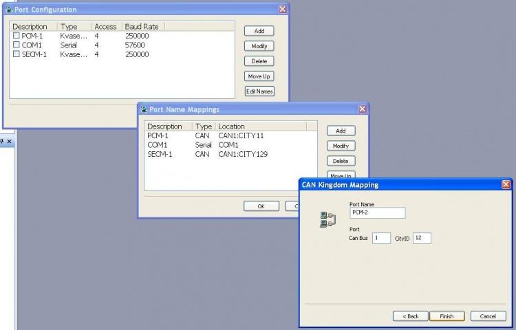
- 1. Right click on the MotoServer satellite icon on the task bar, then right click on Ports.
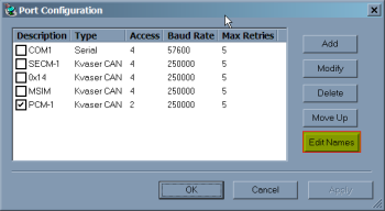
- 2. The Ports Configuration will pop up. Click on 'Edit Names'.
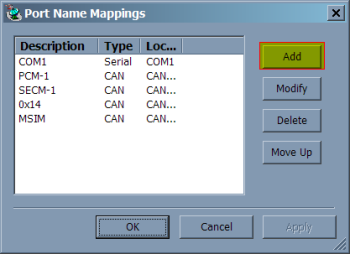
- 3. A new window pops up labeled 'Port Name Mappings'. Click on 'Add' and choose 'CAN Kingdom', then hit Next.
- 4. Give the new location a name (PCM-2 or PCM-B) and set the city ID in decimal. The Windows Calculator can convert between hex and decimal.
MotoTune and Production (Flash) versus Calibratable (Development) Modules
What is the difference in functionality and calibration process, when using a production (PROD) type module versus a development (DEV) type module?
A development module (of the same hardware iteration) is identical to a production module, except it contains a ‘piggyback’ RAM/EEPROM circuit. The purpose of this circuit is to allow ‘real time’ calibration changes and development. This addition is relatively expensive, so it is only applied to modules that need it. Most development is performed on development modules, and the standard Motohawk process assumes their use.
In the case where you need to do work with a production module, it is certainly not a problem. It does have some limitations and minor differences in the software build process, described below.
Limitations:
- A production module cannot support ‘real time’ changes in Mototune or any other calibration tool. Changes must be made offline, and the calibration re-flashed. You can, however, use Mototune to view and record output data.
Build differences:
- When using a production module, a unique Motohawk build is required. In the ‘Target Definition’ block of the current model, under the memory layout dropdown menu, PROD or DEV+PROD must be selected to obtain a build for a production module. If you select DEV+PROD, two *.srz filesets will be produced with a build: one with "_DEV" added to the filename and another with "_PROD" added. Only production module builds can be used to program production modules. Only development module builds can be used to program development modules.
Using a Development versus Flash Controller Summary
Basically, development modules use parallel EEPROM, which is a hardware addition and partly why the development modules are more expensive. When doing calibration from MotoTune, calibration changes are applied immediately (a controlled shutdown isn't required). Doing development on a production module means defining your calibrations as Display NonVolatile (as opposed to constant); in effect, you would be changing values in Serial EEPROM, which would need a controlled shutdown to save. Note that in this case, these calibrations aren't stored in a *.cal file and would need to be re-set on each programming attempt (unlike a development module, where there is calibration management with the *.cal files).
MotoTune Troubleshooting
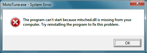
I cannot open MotoTune and I am getting a *.dll error
The mtsched.dll error is generated when a user attempts to open MotoTune without downloading and installing MotoServerRuntime.
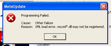
I cannot open MotoTune and I am getting an XML load error
This error is caused when the .net framework 4.0 becomes corrupted or deleted. Re-install the .net framework 4.0 to fix the issue. The .net framework is freely available for download on the web.
What happened to my Compare Calibration screen?
The Compare Calibration or Transfer/Upgrade screen might move off screen for no reason (or if you have had a second monitor hooked up to the computer). This might appear that MotoTune is locked up, but rather the active window is off the screen. To fix the issue take the following action:
- Open MotoTune.
- Open the File menu, then click Preferences.
- In the MotoTune Preferences dialog, open the General tab and click reset.
My Display spreadsheet was gone when I opened the display.
- Right click on the Display treeview.
- Click "Manage Pages..."
- Place a checkbox in the page you would like visible.
My license information is now unlicensed.
Try correcting the issue by starting License Update and canceling a transaction. Why does this fix the issue? The signature in the token may become corrupted, or a user may have started a transaction and never finished it.
Can I export the *.cal directory/parameter structure to Excel or Word?
In today's (9/2007) MotoTune, there is no direct export for calibration files from *.cal to Excel. There is no plan to implement this function. The closest option is a copy and paste of the calibration page into Excel, and the vardec names don't copy with them.
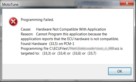
I set the target to this module, but when I tried flashing the program, I got an error.
If you get an error that looks similar to the below image, it means that the software was built with the wrong target module selected. MotoTune can also detect this error if the memory layout is PROD/Flash when it should be DEV/Cal or vice versa. Make sure that the correct controller is selected in the MotoHawk Target Definition block, including memory layout (PROD or DEV).
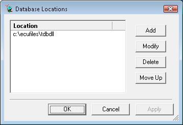
I have installed MotoTune on a machine whose base drive is not labeled C:, how do I get MotoTune to find the ECU files (TDBDLLs)?
To add search locations for TDBDLLs, find the MotoServer icon in the system tray:
Right click on Locations...
Then 'Add' the location by browsing to your custom location(s).
How do I chart and log data in MotoTune?
MotoTune gives the user the ability to real-time chart data and to log data into files for later use. The variables that are charted or logged are the variables pulled into the MotoTune display window. By default, all variables pulled into the window are charted. To deselect all the data points so you can custom select the variables that you want, right click on a value and then click on properties. A screenshot of this is listed below.
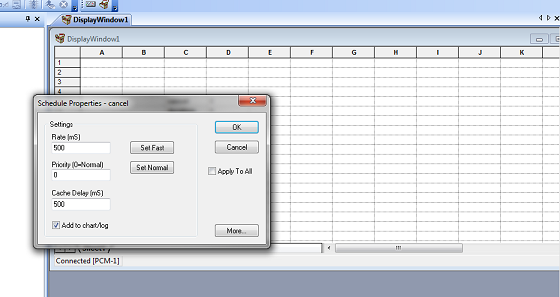
Once you have the properties screen up, deselect the "Add to chart/log" option and then select the "Apply to All" option. Accept the changes. This has now deselected all values. Now, you can open the properties screen again and select the "Add to chart/log" option. It is also a good idea to set the sampling rate of the values you are interested in to be updated quickly. You do not want to set too many values to sample quickly because this can slow down the operation of MotoTune. The sampling rates and number of variables you can sample depends on the type of computer you are using and the system, but it is generally not an issue for people because a lot of variables can be sampled.
Now you can go through and select all the values you want to be charted or logged. You have to do this value by value or by all the values in the window at once. There is no option to choose several values at one time. Once you have selected the values you can now chart/log them. If you want to first setup up the Chart Properties, select the Chart tab and then Chart Setup. To open the chart, go to Chart -> Open Chart, or click on the chart icon on the window selection bar. Once the chart opens, you can see all the values you selected to chart and the value they are at. You can pause and restart charts to collect data in time. To log data, you need to have a chart open, and the data logged will be the same data charted. To log data, you open the chart. Then, when you see data you want to log, click on Chart -> Toggle File Logging option, or click on the Toggle File Logging icon on the window selection bar. When you are done logging the data, click on the Toggle File Logging again. The file will be saved in the logging file under the ECUFiles directory. To change the logging file's name, open the chart setup window. There is an option to name the file. You can also select auto-increment, which will add a number bracketed in parentheses at the end of the file name. This number will increment to keep track of multiple files.
CAN Addressing Conflicts
You may run into issues with MotoTune's CAN messaging conflicting with other CAN communications in your system. It is possible to change the CAN IDs on which MotoTune communicates to avoid this. This section will describe how to do so.
You will need to make changes to both your model and your MotoTune configuration to support the new MotoTune communication CAN IDs.
Model Configuration
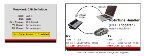
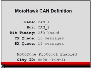
- Disable the MotoTune Protocol in the CAN Definition block
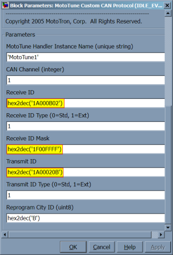
- Add the MotoTune Custom CAN Protocol Handler block (Idle Triggered)
- RX ID = hex2dec('1A000B02')
- RX ID mask = hex2dec('1F00FFFF')
- TX ID = hex2dec('1A00020B')
-
MotoTune Protocol Disabled
-
New CAN IDs for the MotoTune Custom CAN Protocol block
MotoTune/MotoServer Configuration
- Open MotoTune and configure the MotoServer Ports
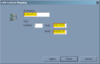
- Edit Port Names and create a Custom CAN Mapping
- TX ID: 436210434 (this is 0x1A000B02, but use decimal here)
- RX ID: 436208139 (this is 0x1A00020B, but use decimal here)
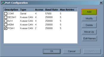
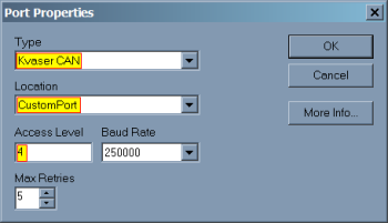
- Create a new Port configuration
- After flashing the module, the MotoTune protocol will no longer be available on PCM-1 and will only be available on the new custom mapping.
-
MotoTune context menu
-
Edit Names
-
Add a port name
-
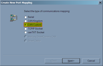
Select 'CAN Custom'
-
Enter your name and the appropriate CAN IDs
-
Add a port configuration
-
-
Now your custom port is in the ports list!
-
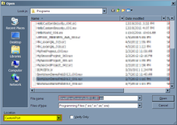
Don't forget to select it in the Program dialog box
MotoTune dongle is plugged in, but MotoViewer won't open.
In order to open up Motoviewer, a separate MotoService dongle is required.
MotoTune has stopped working after a Re-install/Update.
- If you are upgrading from 8.13 to 10.0, please uninstall 8.13 first then install 10.0 if you have encountered issues.
- When downgrading from 10.0 to 8.13, please uninstall 10.0 and the MotoLicense Handler before installing the 8.13 version of MotoTune
Vector CAN
If experiencing problems with running Vector CAN, check the following:
- The setup is correct. Ensure that the Vector CAN Card is correctly connected to the CAN lines, ex:
PC --- Vector CAN Card --- cable --- ECU (128-pin) - Vector CAN installed correctly. Try uninstalling/re-installing.
- The *.dll file is in the correct location. A copy of Vector's VCAND32.DLL needs to be in the same directory as mtvecorcan.dll (defaults to C:\program files\common files\mototron\server).
