Advanced Digital I/O Blocks
C
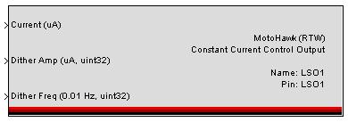
MotoHawk:Blocks:Constant Current Control Output
Supply the numeric parameter values via the Current, Dither Amp, and Dither Freq inputs. Current assigns the output current in uA, while Dither Amp allots a current variance in uA, and Dither Freq allots variance in frequency, in .01 Hz increments.
This block is currently only available on the 112 family of modules, where two LSD's can be configured to use this block.
F
MotoHawk:Blocks:Frequency In
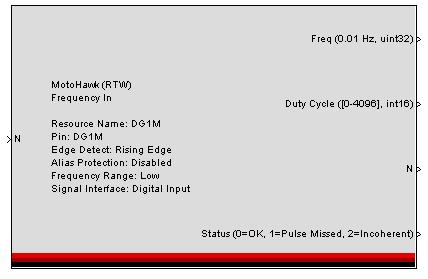
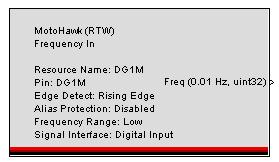
This MotoHawk® block determines the frequency of a digital input signal. The output signal is in units of 0.01 Hz, and is based on the last sample period from edge to edge, with a data type of uint32.
Select a unique resource name. This name can be the name of the sensor that is being read. If none is given, it will either inherit the pin name or the vardec name, depending on whether calibratable I/O is selected.
Choose the pin resource.
Perform Duty Cycle Measurement: Add extra code to perform a duty cycle measurement along with period measurement.
Provide Trigger: Provide a trigger after each N pulses.
Alias Protection: Alias protection is a characteristic that protects low frequency inputs from indicating the incorrect frequency when the frequency is very near the low threshold. It places execution burden upon the Framework because each edge results in the servicing of an interrupt. It should not be employed on inputs that consistently sit above the low frequency threshold under normal operation. The low frequency threshold is set at approximately 1.2 Hz for MPC5xx based modules.
Alias protection will provide guaranteed uniform frequency response for all frequencies between 0 Hz and 39000 Hz. Inputs without alias protection may report incorrectly when they first start up, when they stop and while their frequency is near the low frequency threshold.
The dutycycle describes the elapsed time between the occurrence of the non-synchronous edge and the synchronous edge. The synchronous edge is configured during the creation of the resource via the 'Edge Detect' attribute. 4096 represents 100%
Warning: OSS_VR_Input has an unsupported VR Interface selected in the design
In previous versions of MotoHawk a build warning might appear when a frequency in block with CNK pin and a VR interface is selected. This message is incorrect and should be ignored. This warning was removed in MotoHawk 2012a Beta 4.
check out the MotoHawk FAQs page for more information
MotoHawk:Blocks:Frequency Input Raw 16 Bit Get
This MotoHawk® block reports the raw counts reported by the framework.
If "Get Duty Cycle" is selected, an additional port is displayed.
Choose the resource name (specified in the Frequency Input block) to specify the input channel to reference.
MotoHawk:Blocks:Frequency Input Raw Get
This MotoHawk® block reports the raw counts reported by the framework.
If "Get Duty Cycle" is selected, an additional port is displayed.
Choose the resource name (specified in the Frequency Input block) to specify the input channel to reference.
MotoHawk:Blocks:Frequency In Reference
This MotoHawk® block determines the frequency of a digital input signal. The output signal is in units of 0.01 Hz, and is based on the last sample period from edge to edge, with a data type of uint32.
If "Get Duty Cycle" is selected, then the Frequency Input block must set up the resource to read duty cycle.
Choose the resource name (specified in the Frequency Input block) to specify the input channel to reference.
MotoHawk:Blocks:Frequency Input Trigger
This MotoHawk® block is used in conjunction with the corresponding Frequency Input block. It triggers whenever the selected number of edges have been detected on the pin selected in the corresponding Frequency Input block. When using this block, do not select Alias Protection under the Frequency Input block.
MotoHawk:Blocks:Fuel Injector Sequence
The MotoHawk® Injector Sequence block sets up a sequence of injector drivers starting with the given pin and working up for each driver required by the sequence type. The input ports may be scalars or vectors. If vectors, the size must equal the number of cylinders defined by the Encoder Definition block. This number may be calibratable, in which case the vector must be as large as the Maximum Number of cylinders.
H
MotoHawk:Blocks:High Res One Shot
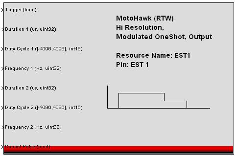
For this MotoHawk® block, when the Trigger input is TRUE, a one-shot digital pulse is generated. The pulse will have 2 periods in which 2 different PWM modulations are generated. Each period is described by Duration, Duty Cycle and Frequency. If the second period duration is 0, then that portion of the pulse is not generated. If the first period is 0, then only the second pulse is generated. If the Trigger input is FALSE, then a new one shot pulse is not triggered. If both pulses have not completed since the previous trigger event, then a new trigger does not occur. When the Cancel input is TRUE, all pulses are canceled. If FALSE, then pulses continue or can be retriggered. Duration is in microseconds, Duty Cycle is in a range of -4096 to 4096 where 0 is 0%, 4096 is 100%, and Frequency is in Hz. When negative duty cycle is applied, the polarity is reversed, which is only valid on PWM resources that are H-Bridge outputs.
MotoHawk:Blocks:High Res One Shot Status
This MotoHawk® block is the High Resolution, Modulated One Shot Status. The name field must match the name of a Hi Resolution Modulated One Shot block. The first port outputs a boolean if all valid pulses have completed. This will ignore pulses with a duration of 0. The second port outputs the last pulse that completed. Once the one shot is retriggered, this is set to 0.
I
MotoHawk:Blocks:Injector Current Select
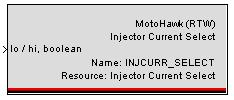
This MotoHawk® block selects the peak-and-hold injector current driver between 3A peak / 1A hold, and 6A peak / 2A hold. This selection is only available on the ECU565-128 module. Input 'false' for 3A peak / 1A hold, and 'true' for 6A peak / 2A hold.
MotoHawk:Blocks:Injector Driver
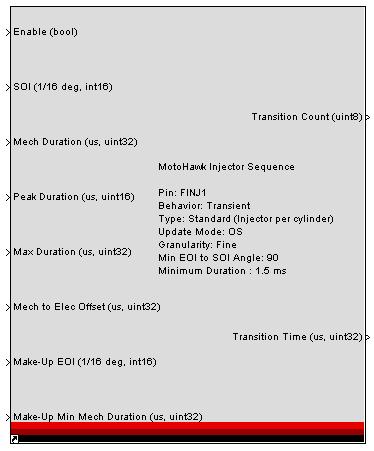
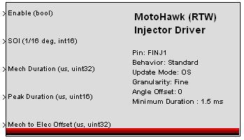
This MotoHawk® block has two similar modes available, Standard and Transient. In Standard mode, a single pulse is generated per cylinder TDC, with an electrical duration of 'Mech Duration' plus 'Mech to Elec Offset', and starting at a crank angle of 'SOI' plus 'Angle Offset'. In Transient mode, up to two pulses are generated. The first pulse is started at SOI, and if the the desired duration rises above the 'Make-Up Min Mech Duration' after the pulse has completed, then a second Make-Up pulse will be generated, ending at Make-Up EOI. If the first pulse has already extended beyond 'Make-Up EOI', the make-up pulse will not be generated.
When using the Transient mode, there must be a separation between the EOI and next SOI that is larger than one crank encoder tooth. Enter an appropriate angle into 'Min EOI to SOI Angle'. 'Angle Offset' is normally the crank angle for the given physical cylinder, in degrees before TDC of cylinder 1. 'Peak Duration' is used with a Low-Impedance Injector, and controls the duration of the peak portion of the pulse. The remaining time is the hold time. The Update Mode selects whether the OS should protect against missing pulses and double pulse generation.
If Application is selected, no error checking is provided, and the application is completely trusted. If OS is selected, some amount of checking is done by the OS. Pulses are only generated while the Enable input is True. When the Enable input goes False, any pulses already started will complete.
This block does not build with the 112 and S12 family of modules. It only works on the 48/80/128 family of modules. This block will be extended to the 112 and S12 modules in a future release of MotoHawk.
MotoHawk:Blocks:Injector Pulse
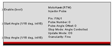
This MotoHawk® block generates a series of pulses, starting at a given encoder crank angle, and either stopping at an angle or after a certain duration. Stop Mode parameter selects which strategy to use. Two of these blocks may be used on a single Injector resource, to generate interleaved pulses, sharing a single pin. Each block must identify the pulse number (0 or 1). If no interleaving is needed, simply use pulse number 0. Pulse Angle Offset is used to apply a fixed offset to the given pulse, relative to TDC. The start and stop angles are then relative to this offset. The Update Mode selects whether the OS should protect against missing pulses and double pulse generation. If Application is selected, no error checking is provided, and the application is completely trusted. If OS is selected, some amount of checking is done by the OS. Pulses are only generated while the Enable input is True. Angle inputs are in units of 1/16th of a degree. Time inputs are in microseconds.
MotoHawk:Blocks:Injector Pulse Complete Trigger
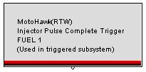
This MotoHawk® block triggers whenever the selected resource completes a pulse.
MotoHawk:Blocks:Injector Sequence
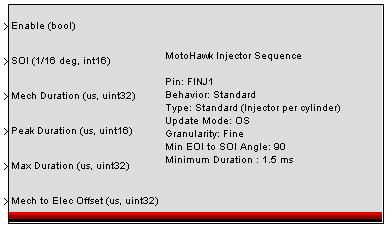
This MotoHawk® block sets up a sequence of injector drivers, starting with the given pin and working up, one for each driver required by the 'Sequence Type'. The input ports may be scalars or vectors, but if vectors, the size must equal the number of cylinders defined by the Encoder Definition block. This number may be calibratable, in which case the vector must be as large as the 'Maximum Number of Cylinders'.
This block does not work with 112 and S12 series of modules. It works only with the 48/80/128 series.
K
MotoHawk:Blocks:Key Off Timer
This MotoHawk® block outputs a uint32 value with units of milliseconds representing the time since last key off.
M
MotoHawk:Blocks:Mux PSP
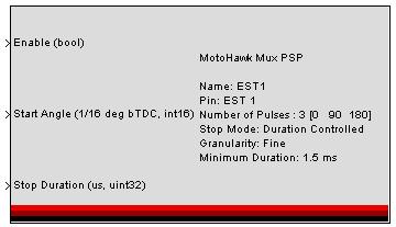
This MotoHawk® block provides an interface to the MuxPSP (Position Synchronous Pulse) behavior in Control Core. The Angle Vector Parameter specifies the scheduled firing of each pulse. The length of the vector also specifies the number of pulses that will be produced. The input ports may be scalars or vectors, but if vectors, the size must equal the number of pulses. The "Name" parameter on this block allows the use of the Mux PSP Set block. This separates the definition from the modifier of the underlying run time attributes.
Due to hardware resource constraints there is some complexity when choosing pins in an application. Please consult the MuxPSP documentation in the Control Core documentation.
MotoHawk:Blocks:Mux PSP Set
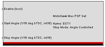
This MotoHawk® block can modify the original resource specified by 'Name'. A Mux PSP block must be in the model for this block to function properly.
Note: Mux PSP Modes
PSP block has 2 modes-hard start and hard stop, hard start and hard duration.
Hard Start – Hard Stop : This is Angle/Angle control, but the starting and ending angles are strongly enforced. There is also an optional maximum duration that is used as a backup ending condition for a pulse. This is intended to protect against pulse overlap and extra-long pulses during changing RPMs.
Hard Start – Hard Duration :
This is Angle/Duration control, but the starting angle and the duration are strongly enforced. There is also an optional maximum angle that is used as a backup ending condition for a pulse. This is intended to protect against pulse overlap and extra-long pulses during changing RPMs.
0
MotoHawk:Blocks:One Shot Output
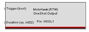
When the Trigger input is TRUE, this MotoHawk® block generates a one-shot digital pulse. The Duration input specifies the length of the pulse in microseconds. Most modules can only use this block with a pulse duration of the RTI. To make custom pulse widths you need a module with a TPU. The 48, 80, and 128 modules do not have this capability and the 112 module does. To see if other modules have this capability contact New Eagle.
Q
MotoHawk:Blocks:Quadrature Block Set
Just to note the Quadrature Block set has been deprecated in recent versions of MotoHawk, but is still included in the installation. If you want to access this block set go to 'Files\Woodward\MCS\MotoHawk\2011b_sp0.223\Blocks\Deprecated)' where 2011b_sp0.223 is the version of MotoHawk you are using. This folder will contain all the necessary files to use the quadrature blocks, just add the ones you need to the Matlab path.
MotoHawk:Blocks:Quadrature Decoder
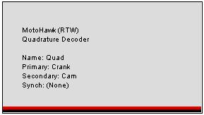
This MotoHawk® block configures the Quadrature Decoder behavior which determines the position of a transition-count or quadrature encoder device.
There are three possible resources that are available, primary, secondary and synch. The primary and secondary determine the speed and direction of the sensor while the synchronize (optional) is a pulse input. The synchronize input can be linked to a trigger when it occurs.
There are two counters that can be used to track an encoder that overflows the internal counter between reads. The first counter rolls over after "Edge Count Rollover" counts and forces an increment of the second counter or the "Modulus Counter." The second counter resets to 0 after "Modulus Counts."
So, with edge modulus count set to 100 and modulus count set to 10 and 150 edges, then the modulus counter is set to 1 and the edge count is set to 50. The Period Option selects when the period and position count is updated.
- "All Edges" : Updated every edge on both input channels
- "Primary Edges" : Updated every edge of the primary channel (falling and rising)
- "Primary Rising Edge": Updated every rising edge of the primary channel
MotoHawk:Blocks:Quadrature Decoder Enable Resynch Set
This MotoHawk® block reenables or disables the synchronization trigger.
MotoHawk:Blocks:Quadrature Decoder Enable Set
This MotoHawk® block enables or disables the quadrature decoder behavior. By default, the behavior is enabled.
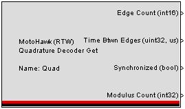
MotoHawk:Blocks:Quadrature Decoder Get
This MotoHawk® block determines the position of a transition-count or quadrature encoder device. It outputs the current edge number and the period between the most recent two edges.
MotoHawk:Blocks:Quadrature Decoder Position Set
This MotoHawk® block overrides the current edge count of the quadrature decoder behavior.
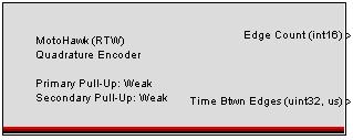
MotoHawk:Blocks:Quadrature Encoder
This MotoHawk® block determines the position of a transition-count or quadrature encoder device. It outputs the current edge number and the period between the most recent two edges, and uses the CRANK/CAM pins on ECU modules, or TISS and TOSS, if available, on other modules. The Period Option selects when the period and position count is updated. "All Edges" : Updated every edge on both input channels "Primary Edges" : Updated every edge of the primary channel (falling and rising) "Primary Rising Edge": Updated every rising edge of the primary channel
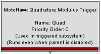
MotoHawk:Blocks:Quadrature Modulus Trigger
This MotoHawk® block triggers a Simulink Function-Call subsystem when the modulus counter rolls over. More than one trigger may be placed in a model hooking off of the same event. In this case, the 'Priority Order' can be used to order these independent triggers. If the priorities are the same, then the order is determined by Simulink.
Checking 'This trigger is inside another triggered subsystem' will attempt to simulate the block inside of another triggered rate, when the rate is periodic. The most common reason to check this is to place a background periodic task inside of a foreground periodic task, or vice versa. The trigger from this block may occur in bursts, synchronized to the outer rate, while simulating, but will perform as expected on the target.
Note that 'This trigger is inside another triggered subsystem' should not be checked on top-level triggers, otherwise the block will not simulate at all.
If this trigger is used inside of a containing subsystem, normally the triggered subsystem will pause and resume based on the enable/disable status of the containing subsystem. Checking 'Trigger even when containing subsystem is disabled' will cause triggers to occur even while the parent is disabled. Note that this feature will not simulate, but will execute correctly on the target.
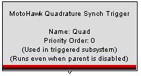
MotoHawk:Blocks:Quadrature Synch Trigger
This MotoHawk® block triggers a Simulink Function-Call subsystem when the synchronize edge is encountered. More than one trigger may be placed in a model hooking off of the same event. In this case, the 'Priority Order' can be used to order these independent triggers. If the priorities are the same, then the order is determined by Simulink.
Note that 'This trigger is inside another triggered subsystem' should not be checked on top-level triggers, otherwise the block will not simulate at all.
If this trigger is used inside of a containing subsystem, normally the triggered subsystem will pause and resume based on the enable/disable status of the containing subsystem. Checking 'Trigger even when containing subsystem is disabled' will cause triggers to occur even while the parent is disabled. Note that this feature will not simulate, but will execute correctly on the target.
S
MotoHawk:Blocks:Spark Sequence
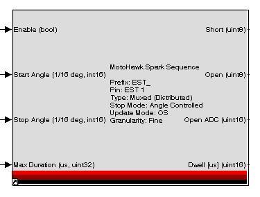
This MotoHawk® spark coil sequence block sets up a sequence of spark coil drivers starting with a given pin and working up. The input ports may be scalars or vectors. If vectors,the size must equal the number of cylinders defined by the Encoder Definition block. This number may be calibratable in which case the vector must be as large a the Maximum Number of Cylinders
When the diagnostics outputs are enabled, open and short circuit detection becomes available. The open and short outputs are one of the 3 possible states
- 0 ⇒ OK
- 2 ⇒ Indeterminate
T
MotoHawk:Blocks:Tachometer
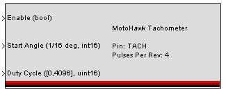
This MotoHawk® block outputs a train of pulses synchronized to engine RPM, with a variable pulse width, and variable start angle relative to TDC1.
Enter the number of pulses per engine crank revolution. If "Dynamic Create" is checked, this resource will be created the first time this block is executed.
V
MotoHawk:Blocks:Variable CAM Phase
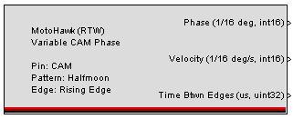
This MotoHawk® block determines the phase, velocity, and time between edges of a CAM input. Choose the pin resource.
Note that if CAM is selected as the resource, reading the phase will be combined with engine synchronization. Only very few encoder patterns support both variable-cam phasing and engine synchronization. See the encoder definition block.
MotoHawk:Blocks:Variable CAM Trigger
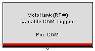
This MotoHawk® block provides a trigger whenever a CAM edge is detected, as setup in the Variable CAM Phase block. Either choose the resource to reference, or provide the name of a resource by name, as defined by a Variable CAM Phase definition block.
