CAN Blocks
MotoHawk:Blocks:CAN Definition Block
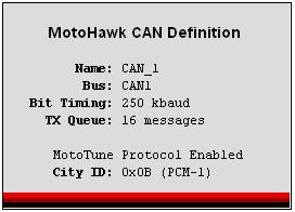
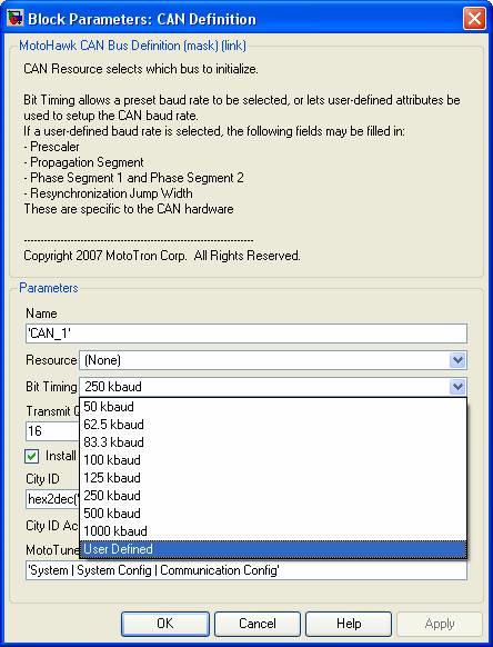
Use this MotoHawk® block to select which CAN bus to initialize and define. CAN_1 is available on most ECUs, but CAN_2 and even CAN_3 are also available on some. See specific ECU datasheet for CAN information. Use this block's Bit Timing to select a preset baud rate, or have user-defined attributes set up the CAN baud rate. If a user-defined baud rate is selected, these fields are definable:
- Prescaler
- Propagation Segment
- Phase Segment 1/2
- Resynchronization Jump Width
Each CAN RX block includes an ID, which is used in combination with the mask. Only the bits set to 1 in the mask for the corresponding buffer are compared when detecting a received message. If a Queue Size of zero is input, then no queue will be attached. Check Install MotoTune Protocol to use MotoTune over the given CAN interface.
MotoHawk:Blocks:CAN Fault Status Block
This MotoHawk® block reports the current fault status of the selected CAN resource. "Bus Passive" is true when the bus is disconnected, shorted, improperly terminated, the baud rate is incorrect, or if bit error rates are high enough to cause hardware failures. "TX Error Counts" is 0 when the bus is operating properly and greater than 0 when the module is unable to transmit CAN messages. "RX Error Counts" is 0 when the bus is operating properly and greater than 0 when the module is unable to receive CAN messages.
MotoHawk:Blocks:CAN Read Message Block
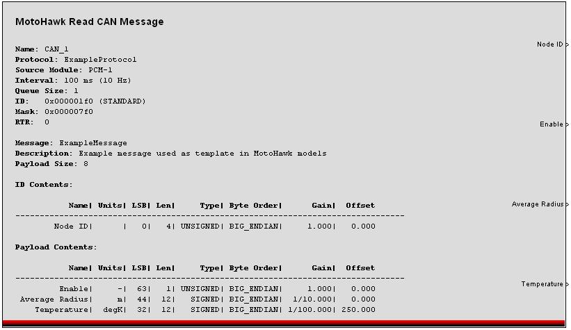
This MotoHawk® block will receive and unpack a CAN message on the selected CAN channel. Attach Simulink signal specifications the output ports, to convert the output signals to an appropriate data type. Specifically, if a gain or offset is applied in the message specification, assign the signal to the floating-point data type.
Physical CAN Channel: The physical channel on which to transmit
Message Definition: A structure or a cell array of structures describing all of the details of 1 or more CAN messages. See motohawk_can_example.m for precise details of the structure.
Queue Size: This sets the size of the incoming message queue that will hold messages until this block executes. A value of zero or one will make only the most recently received message available.
Slot Name: The slot name can be used to connect this block to a slot which can be used to dynamically adjust the ID, ID Mask, Payload, and Payload Mask values.
Show Data Available Port: If selected a port will be added that will have the value 1 if a message is available and zero otherwise. If the queue size is larger than 1 than you can hook a Simulink Do-While block to this port and poll all of the messages out of the Queue.
Show Age Count Port: This port will increment every time the block executes and no messages are available. The date from this port can be used to do timeout logic on a message.
Label Wires with Field Names: Selecting this checkbox will cause the field names to be applied to the wires leading out of the block.
MotoHawk:Blocks:CAN Receive Slot Properties Block
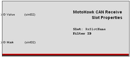
This MotoHawk® block allows the user to configure the slot properties at run time.
MotoHawk:Blocks:CAN Send Message Block
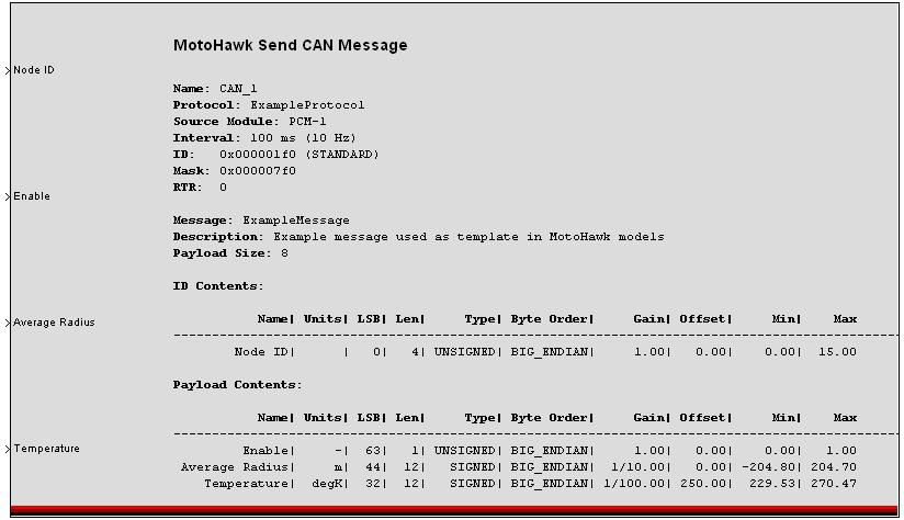
This MotoHawk® block will pack and transmit one or more CAN messages on the selected CAN channel.
Name: The name of the CAN channel on which to transmit that is defined in a CAN definition block.
Message Definition: A structure or a cell array of structures describing all of the details of 1 or more CAN messages. See motohawk_can_example.m for precise details of the structure.
Pacing Interval[ms]: The time to delay between transmitting messages for a multiple message group. The pacing interval will insert the selected amount of time between each message if an array of messages has been specified. The group of messages will be transmitted at the interval defined in the message structure but will have an inter-message delay of the Pacing Interval. If the number of messages multiplied by the pacing interval is longer than the message interval, the latter messages will be dropped the cycle restarted with the first message in the group.
The interval in the .m file can be set to -1 to inherit the rate of the subsystem which contains the CAN Send block. The interval can also be set to a fixed value which sets the minimum time to be waited before a message is sent. On the Classic Modules, 48, 80, and 128 pin, there is a 'fuzz' time that is hardcoded to be 500us subtracted from this time. This means a task will send the message if the time since the last message was sent is greater than the interval minus the “fuzz”. So a 100ms interval will result in a message being sent if 99.5 or more milliseconds have elapsed since the last time the message was sent. The interval is evaluated at the rate defined by the subystem that houses the MotoHawk CAN Send block. Scheduling is affected by both the granularity of the trigger that houses the CAN Send block and also by the other execution that is occuring within the system. CPU load can have an impact on the observed interval and a delay of up to one trigger rate is possible. Below is an example of an extreme case: Consider a system with a 20ms trigger. Normally there is 5ms of work executed and then the expiry check occurs. Every now and then there is some variable work that executes too. In my example this is also 5ms of work. The additional delay of 5ms means that when I next check for expiry under normal loading I fail the expiry test because 100ms has not yet expired. Thus the message is delayed by the execution interval, which in my case is 20ms. The variable work would be of no consequence if it executed in the earlier trigger. It is because it executes before the test that will expire that we have the problem.
Label Wires with Field Names: Selecting this checkbox will cause the field names to be applied to the wires leading into the block.
MotoHawk:Blocks:CAN Send Message Raw Block
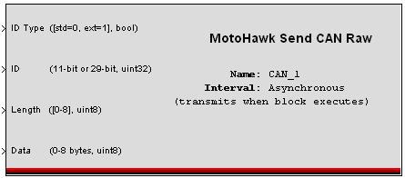
This MotoHawk® block is analogous to the Read CAN Raw block except that it transmits messages on the CAN bus instead of reading them. For single frame messages, the more advanced Send CAN Message block is typically preferred instead since this block does not perform any bit packing. It can be useful, however for sending multi-frame messages where data spans multiple CAN frames using the same message ID.
MotoHawk:Blocks:CAN Slot Trigger Block
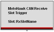
This MotoHawk® block triggers whenever a CAN message is received on the given Slot.
Workflow of developing CAN using MotoHawk
There are a couple of workflows to consider for MotoHawk and CAN
a. DBC file -> DBC to M converter -> MotoHawk manipulation to Simulink. This is a standard product New Eagle offers to generate M files. You can purchase DBC files externally or create them using a 3rd party DBC file editor
b. MotoHawk CAN primitives. Create messages from scratch using the MotoHawk CAN blockset.
c. DBC Networking Toolbox - Convert a DBC file -> Simulink model. This is a New Eagle product: Webstore: DBC Networking Toolbox
Show an example of configuring the MotoHawk CAN Block
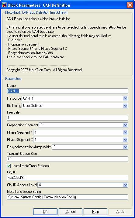
Those settings are exposed by the custom CAN baud rate selection:
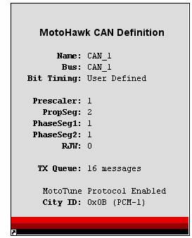
Here is an example of the block correctly configured for 500 kbaud operation on a ECM5554:
CCP CAN Protocol Handler
- Click on the following link to view block description:
Motohawk Calibration with INCA
Usage of ETAS software/hardware (INCA/ES580, 581) with MotoHawk software/hardware?
INCA can be used to calibrate the modules once it's been programmed using MotoTune.However, for that, the model that generated code must contain MotoHawk CCP Handler blocks. In order to read how, please refer to the pdf below.
ETAS ES581 should work fine with CCP calibration of our modules in INCA and in fact, will be used when working with INCA, but it can't be used for programming the module. Kvaser tools are used for programming the modules.
- Click the following link to download the document on steps for using INCA as a calibration tool.
Motohawk Calibration with INCA
Usage of Vector tools with MotoTools (MotoTune/MotoService)
The Vector hardware will (or, at least used to) operate under a common API, so either the CANCardX, CANCardXL and CANCase would all work with MotoTune. Vector Hardware is not compatible with Win 7 and currently, MotoTools don't support 64-bit operating systems on vector hardware.
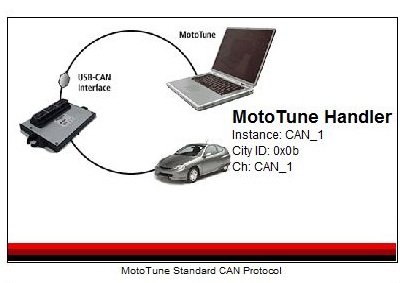
MotoTune Handler Library
This library allows the user to customize the MotoTune CAN protocols for your system. An example of when this library would be useful, is when MotoTune is conflicting with other messages on the BUS. The library consists of the standard CAN protocol, custom user defined protocol, and idle_event triggered versions of each. The idle event trigger has MotoTune communicate with the module in idle periods of bus use. This can be useful when the BUS usage is high, and it is not vital to update values in MotoTune. However, the MotoTune Handler library does not work with the 24 and 112 pin modules. To download the library click on the link below.
Products:
To see the products that we provide to help with your CAN communications and CAN interfacing go the CAN Development page located here CAN Development.
