Encoder Blocks
A
MotoHawk:Blocks:Average RPM
This MotoHawk® block outputs the Average RPM with a data type of uint16. It is calculated based upon the time taken to traverse from one firing TDC to the next. It shall output zero until encoder synchronization has been achieved.
C
MotoHawk:Blocks:Current Number of Cylinders
This MotoHawk® block outputs the current number of cylinders, as calibrated in the Encoder Definition block. This number will not change while the program is executing. This number may be smaller than the Maximum Number of Cylinders, if the number of cylinders is calibratable.
D
MotoHawk:Blocks:TPU Encoder Patterns
MotoHawk™ has features specially designed to synchronize to rotating machinery, such as the crankshaft of an internal combustion engine. It does this by monitoring electronic signals from a crank sensor and/or a cam sensor. A crank sensor is mounted near a crank encoder wheel, which has teeth like a gear, but usually has a pattern encoded into the teeth. This pattern allows MotoHawk™ to calculate not only how fast the engine crankshaft is spinning, but to also decipher instantaneous crank angle engine position.
The Encoder Definition block configures ControlCore so that it may perform such engine synchronization tasks for all the SupportedEncoders Supported Encoders. Other MotoHawk™ blocks in the Encoder Blocks group allow access to engine speed, the current engine position, the encoder synchronization state, notification of an encoder fault and what encoder fault occurred. Other blocks can adjust the top-dead-center (TDC) offset or the phase at runtime. Crank synchronous triggers are also made available via the MotoHawk ™ Trigger block.
E
MotoHawk:Blocks:Encoder Angle
This MotoHawk® block outputs the current encoder angle in 1/16 degrees before TDC.
MotoHawk:Blocks:Encoder Angle Extrapolation
MotoHawk:Blocks:MotoHawk Encoder Definition Block
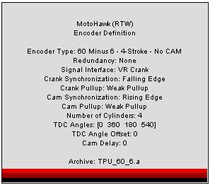
MotoHawk™ has features specially designed to synchronize to rotating machinery, such as the crankshaft of an internal combustion engine. It does this by monitoring electronic signals from a crank sensor and/or a cam sensor. A crank sensor is mounted near a crank encoder wheel, which has teeth like a gear, but usually has a pattern encoded into the teeth. This pattern allows MotoHawk™ to calculate not only how fast the engine crankshaft is spinning, but to also decipher instantaneous crank angle engine position.
The Encoder Definition block configures ControlCore so that it may perform such engine synchronization tasks for all the Supported Encoders. Other MotoHawk™ blocks in the Encoder Blocks group allow access to engine speed, the current engine position, the encoder synchronization state, notification of an encoder fault and what encoder fault occurred. Other blocks can adjust the top-dead-center (TDC) offset or the phase at runtime. Crank synchronous triggers are also made available via the MotoHawk ™ Trigger block.
MotoHawk:Blocks:Encoder Fault
This MotoHawk® block outputs the last encoder fault that has occurred.
0: No Fault Has Occurred
1: Crank Synchronization Fault - Indicates that the teeth seen do not match the tooth pattern as setup in the Encoder Definition block.
2: Reverse Rotation Fault - When the encoder pattern is rotating in reverse relative to the selected tooth pattern.
3: No Crank Edges Fault - Indicates that no edges are seen on the Crank pins, but edges are seen on the CAM pins (only available when a CAM sensor is used).
4: No CAM Edges Fault - Indicates that CAM edges are not being detected, but Crank teeth are visible.
5: CAM Synchronization Fault. The CAM edges are not aligned properly to the Crank angle. Either the wrong pattern is being used (half-moon vs. single-tooth), or the CAMDelay calibration may need adjustment.
6: Encoder Sync error on Slave. Only available in a dual redundant encoder system. This error is issued when a synchronisation fault is detected on the slave encoder channel.
7: Reverse rotation on Slave. Only available in a dual redundant encoder system. This error is issued when the primary encoder source of the slave channel is indicating reverse rotation.
8: Primary Slave Encoder Loss. Only available in a dual redundant encoder system. This error is issued when no encoder edges are observed on the slave encoder.
MotoHawk:Blocks:Encoder Fault Trigger
This MotoHawk® block triggers whenever an encoder fault occurs. The triggered subsystem may use the MotoHawk Encoder Fault Status block to get the value of the actual fault that has occurred.
MotoHawk:Blocks:Encoder Phase
This MotoHawk® block sets whether the underlying pulse generation system is in or out of phase with the actual engine. Camless 4-stroke crank encoder patterns do not allow, by themselves, a means to determine what half-cycle an engine is operating in. When teeth are detected through rotation the underlying encoder sub-system makes a guess. This guess is either correct or off by 360degCA. Other systems, outside the encoder sub-system, can sometimes be used to determine whether the encoder sub-system has guessed correctly.
Set this to true when the guess is incorrect.
MotoHawk:Blocks:Encoder State
This MotoHawk® block outputs the current state of the encoder synchronization algorithm.
1: ZERO_SPEED
2: POSN_UNKNOWN
3: ENC_SYNC_CAM_UNKNOWN
4: ENC_SYNC_CAM_SYNC
5: ENC_SYNC_MASTER_ONLY
6: ENC_SYNC_SLAVE_ONLY
7: ENC_SYNC_DUAL
MotoHawk:Blocks:Encoder State Trigger
This MotoHawk® block triggers whenever the encoder state changes, such as from ZERO_SPEED to POSN_UNKNOWN. The triggered subsystem may use the MotoHawk Encoder State block to get the value of the new state.
MotoHawk:Blocks:Encoder TDC Offset
This MotoHawk® block sets the global encoder TDC offset in 1/16 degrees before TDC. This can be used at run-time, for example, to add 360 degrees to change the CAM phase. Usually this is connected to a Calibration block, so that the mechanical vs. electrical TDC offset can be tuned.
NOTE: The CAM phase may be interpreted differently depending on module. Beware when porting between modules as TDCOffset may need to be changed by 360 degrees.
Example modules exhibiting this difference are PCM128 and ECM112.
MotoHawk:Blocks:Flex Encoder
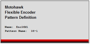
The Flexible Encoder allows the user to specify their exact Encoder Specification using an xml file. Also, classic encoder patterns as defined in the Encoder Definition Block are generic. For example, the 60-2 crank; single tooth cam was the same for all users. There was no way to tune the encoder behavior based on system characteristics. With Flexible Encoder, the overall encoder design is shifted to the customer. Therefore, the encoder can be designed for the customer specific application. Teeth location, Keying/Pattern matching, Fault behavior, Impact of Wheel Acceleration, Source Interaction, .. can all be specified specific to the user's application.
I
MotoHawk:Blocks:Instant RPM
This MotoHawk® block outputs the instantaneous RPM with a data type of uint16. Instant RPM is the most accurate instantaneous measure. It is calculated using the most recent high resolution measure of the time taken to traverse two encoder teeth. The calculation is performed automatically by the framework when the request is made. It is also cached so that repeat calls do not result in the calculation repeating when its data has not changed. Instant RPM will report a non-zero engine speed once encoder teeth have been observed.
M
MotoHawk:Blocks:Maximum Number of Cylinders
This MotoHawk® block outputs the maximum number of cylinders by the design, as setup in the Encoder Definition block. This number will not change while the program is executing. This number may be larger than the Current Number of Cylinders, if the number of cylinders is calibratable.
P
MotoHawk:Blocks:Pseudo Encoder
This MotoHawk® block controls the software simulation of the crank encoder. When Enable is true, the RPM is applied, and real crank encoder teeth IO signals are ignored. RPM is a uint16. The MotoHawk® Encoder Definition block is required to use the Pseudo Encoder.
S
MotoHawk:Blocks:Secondary Encoder TDC Offset
This MotoHawk® block sets the global encoder TDC offset in 1/16 degrees before TDC. This can be used at run-time, for example, to add 360 degrees to change the CAM phase. Usually this is connected to a Calibration block, so that the mechanical vs. electrical TDC offset can be tuned.


