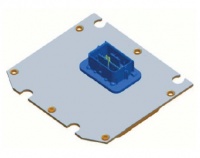
SECM70
ECM-5634M-70
Product Summary
The SECM70 control platform fits a variety of applications, including gasoline and
natural gas engines for power generation, forklifts, lift trucks, and on-highway
vehicles. The SECM70 control is programmed to meet the specific needs of the
prime mover and its driven load.
The SECM70 control consists of a single rigid printed circuit board attached to an
aluminum housing using thermal adhesive, which is then closed and sealed with
an aluminum cover. Connections to the control are made via a single 70-pin
automotive-style sealed connector. The control can be mounted directly to the
engine or frame using vibration isolators which are available pre-installed on the
control or separately.
- Features include:
- 70-Pin platform
- Microprocessor: ST SPC563M64, 80 MHz
- Memory: 1.5 M flash, 94 K RAM, 16 K serial EEPROM
- Operating Voltage: 8–32 Vdc, 36 V (jump start), 5.5 V (crank)
- Operating Temperature: –40 to +105 °C
Datasheets
Software Variant Features
15xx Modules
- Available since MotoHawk 2015a SP0 or newer
- Improved diagnostic on LAMP pins
- Increased UEGO resolution and accuracy
- Increased switching speed on LSO4/5/6/7 and H2
- Allow LSO4/5/6 to drive inductive loads
- Modules that support UEGO expose an additional internal ADC resource for FVOUT. This provides the user an option to use a slightly higher resolution reading.
- Hardboot firmware version 2.08
- The factory installed application supports XCP communications and reflashing using CAN_2 at 500k with CRO = 0x188C0CF9 and DTO = 0x188BF90C
- Reprogramming supported on CAN2
Compiler
Green Hills version 4.2.4
GCC for PowerPC EABI-SPE version 4.6.0
BootKey
A malfunctioning application previously loaded on the SECM70 can be recovered using the BootKey recovery.
The BootKey signal needs to be connected to the SWG4 pin.
Bootstrap
The SECM70 can be forced to remain in the firmware bootloader by applying a bootstrap sequence. The bootstrap sequence is:
| Pin | State for Boot |
|---|---|
| AN1 | High |
| AN2 | High |
| AN3 | High |
| AN4 | |
| AN5 | |
| AN6 | |
| AN7 | |
| AN8 | |
| AN9 | Low |
| AN10 | Low |
| AN11 | Low |
Frequently Asked Questions/Topics
Is the Marine variant suited for sensorless 3-phase brushless motor?
To introduce this answer, we review that it is possible to run a 3-phase brushless DC motor with and without position sensors. A position sensor can directly indicate the position of a motor shaft. Sensorless systems are advanced enough to determine the position of the shaft through back-EMF waveforms, although complexity will increase greatly under very small signal to noise ratios (when the motor is just starting and at very slow speeds.)
Engineers have design protected for sensorless 3-phase brushless DC motor operation in SECM70, but the Marine variant is not suited for this application.
The Marine variant SECM70 should always be designed to operate a 3-phase brushless motor with hall position sensors connected to module pins 56,57,58 for PhaseC, PhaseB, PhaseA, respectively. MotoHawk Input Capture blocks can then be used with the resources MotorPhaseVSense_A, MotorPhaseVSense_B, and MotorPhaseVSense_C. The Input Capture behavior allows the application to be notified of an input pin state change, which correlates to a sample every 60 degrees. The algorithm to calculate motor position and speed is outside the scope of what MotoHawk is providing in support of this module.
Can I diagnose PWM EST outputs?
Due to the nature of the hardware, EST diagnostics are only available when driven as a sequence and not as a PWM.
The ESTs have a caveat that certain groups must not turn off at the same time as there is shared diagnostic HW.
The groupings where you should avoid turning off at the same time are:
EST 1,2
EST 3,4
EST 5,6,7,8
Why is LSO6 current sense not working?
On modules that support current sense for the resource LSO6, the load must be connected to pin 11. Pin 10 is also connected to the LSO6 driver but before the current measurement sense resistor and therefore current will not be measured.
How is LSO3 different than LSO6/LSO7 on the Marine variant?
LSO3 current sense is only able to measure current when the driver is in the On state. This is common to all the module variants. The Marine variant has additional current sense for LSO6 and LSO7. The current measurement at pins 11 and 15, respectively, will measure the current when the driver state is On and Off.
How would you use the H1GATE_ENABLE output?
The H1GATE_ENABLE can be used to reset the ASIC responsible for driving H1 the SECM70. If H1GATE_ENABLE is not referenced in the application, then by default it will always be set in an enabled state. If a reset of the ASIC is necessary, it is suggested to set H1GATE_ENABLE to false (logic 0) for one RTI period and then return H1GATE_ENABLE to true (logic 1).
Why do I see a high current on H1 when in Fault or H1GATE_ENABLE is disabled?
Current measurement is obtained by sampling analog outputs from the ASIC. These outputs are centered at 2.5V such that +ve and -ve currents can be reported. However when in fault or disabled, the analog output channel goes to 0V and therefore is reported to have Max current.
Other Engine Control Modules
More Information: Engine Control Modules
