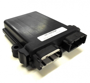
VPIM
Overview
The New Eagle™ Vehicle Power Interface Module (VPIM) provides the necessary circuitry to interface with Electric or Plug-In Hybrid Electric (EV/PHEV) vehicles charging equipment in accordance with the SAE J1772 specification. The VPIM allows the vehicle systems and ECUs that require a low current "Sleep" mode to be managed externally by the VPIM. The VPIM monitors the charging interface inputs and provides an output signal that can drive an external "Wake Up" signal to the related vehicle systems.
The VPIM also supplies feedback in the form of conditioned PWM and Analog signals to the vehicle system(s) which control the flow of energy from the charger to the vehicle. The analog feedback is output in the form of a 0V to 5V DC signal proportional to the duty cycle of the PWM Input. Also, a PWM feedback is available which rectifies the SAE J1772 +/- 12V PWM signal into a 0 – 9V(max) PWM signal that can be read by most standard ECUs.
The VPIM provides a path to control the state of the off board charging station. When a pin on the VPIM is asserted to ground via a low-side drive or relay by the ECU, the charge station will provide the Level 1 or Level 2 charging voltage.
Features include:
- Operating Voltage: 8-14 VDC
- J1772 Hardware Interface
- Low Current Consumption < 10mA
- Operating Temperatures ranging from -40°C to 105°C
In an EV with an on-board charger, why is the VPIM required? Some on-board chargers are not up to date on the J1772 specification. The VPIM allows the charge station contactors to activate, thus enabling charge voltage to be applied to the vehicle.
Improvements to New Revision 0.8 VPIM
- Many Easily Configurable Features. The latest VPIM has a number of features that can easily be configured by shorting (or leaving open) different pins in the header. No soldering is required nor must the circuit board be removed from the enclosure. Therefore, some of the features of the VPIM can be reconfigured throughout the development process as customer needs evolve.
- The High Side Drive can be configured to shut off after approximately 30 seconds. This timer circuit was replaced with a more stable and robust timing solution. The timer feature can be enabled or disabled through the harness.
- A low battery voltage feature was added such that the High Side Drive (HSD) wakes up if the voltage input level (i.e battery voltage) drops below a certain threshold (e.g. 9V). Turning on the HSD will wake up the supervisory controller, which commands the high voltage battery pack to charge the 12V battery through a DC-DC converter. The low battery voltage threshold can be set through the harness to any of the following levels: 9.96V, 10.44V, 10.53V, 11.01V. The low battery feature can be disabled through the harness as well.
- Previous board revisions contained different functionality for different customers. VPIM rev 0.8 combines the features of all previous revisions into a single configurable boards. These configurable features can be set through the harness.
- The accuracy of the PWM to analog circuit that reports the control pilot duty cycle has been improved.
- The rev 0.8 VPIM has a second PWM to analog circuit for use with a low side drive. This ancillary PWM to analog circuit can be used however the customer sees fit.
- The accuracy of the "State B" and "State C" voltage levels was improved.
- An additional proximity signal pin has been added (pin 13). A second proximity signal pin is beneficial because it eliminates the need to "T" off of the proximity signal wire in the harness. One pin can be thought of as an input pin that connects the resistor network in the charge coupler to a voltage divider in the VPIM. The second pin can be thought of as an "output pin" that reports the proximity signal voltage (i.e. charge coupler connection status) to the vehicle supervisor. Keep in mind, however, that pins 6 and 13 are internally connected, so it does not matter which pin is used as "input" and which pin is used as the "output."
- ESD protection has been added to all of the inputs and outputs.
- Over-voltage protection has been added to the VPIM and is enabled when the supply voltage exceeds 16V. All downstream circuitry is protected in an over voltage event.
- Reverse polarity protection has been added to the VPIM.
Part Number History
VPIM Module Prototype VPIM-012-1006
VPIM Module Rev 0.6 VPIM-012-1202
VPIM Module Rev 0.7 VPIM-012-1201
VPIM Module Rev 0.8 VPIM-024-1301
Frequently Asked Questions (FAQ)
Q: What is the connector on the VPIM?
A: The VPIM Connector kit is the CON-KIT-DTM24. It is a standard Duetsch DTM06 connector.
