IO Devices: Difference between revisions
| (228 intermediate revisions by 11 users not shown) | |||
| Line 1: | Line 1: | ||
==Introduction == | ==Introduction == | ||
New Eagle carries or can build or | New Eagle carries or can build or source Input/Output (I/O) devices for your application. Please read below about current offerings or contact '''[http://neweagle.net/contact/ sales]''' to discuss your needs. | ||
Datasheet or user manual not available? Check out the '''[[Other_Datasheets|Additional Downloads]]''' or please visit our '''[https://support.neweagle.net/support/home Support Portal]'''. | |||
==System Input Modules== | ==System Input Modules== | ||
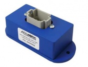
===1 Universal Signal Input to CAN=== | ===1 Universal Signal Input to CAN=== | ||
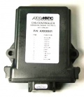
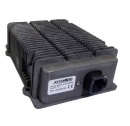
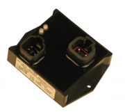
The 1 Universal Signal Input Module measures | The 1 Universal Signal Input Module measures one universal signal input (Voltage, Current, Resistive, Digital, Frequency, or PWM) and outputs the value over CAN. This device is J1939 compliant and can be configured with the Axiomatic Electronic Assistant PC tool. | ||
{| class="wikitable" style="text-align: center;" cellpadding = "5" | {| class="wikitable" style="text-align: center;" cellpadding = "5" | ||
| Line 16: | Line 17: | ||
!scope="col" style = "width:180px;"|Part Number | !scope="col" style = "width:180px;"|Part Number | ||
!scope="col" style = "width:180px;"|Webstore | !scope="col" style = "width:180px;"|Webstore | ||
!scope="col" style = "width:180px;"|Downloads | |||
!scope="col" style = "width:180px;"|More Information | !scope="col" style = "width:180px;"|More Information | ||
|- | |- | ||
| Line 24: | Line 26: | ||
AX030530 | AX030530 | ||
|style = "height:150px; width:180px;"| | |style = "height:150px; width:180px;"| | ||
'''[ | '''[https://store.neweagle.net/shop/products/input-output-devices/1-analog-signal-input-to-can-sae-j1939/ Purchase]''' | ||
|style = "height:150px; width:180px;"| | |style = "height:150px; width:180px;"| | ||
'''[ | '''[[System_Input_Modules_Downloads#1_Universal_Signal_Input_to_CAN | Datasheet]]''' | ||
|style = "height:150px;"| | |||
'''-''' | |||
|- | |- | ||
|[[File:AX030530.JPG|180px]] | |[[File:AX030530.JPG|180px]] | ||
| Line 36: | Line 40: | ||
'''Please contact [mailto:sales@neweagle.net sales]''' | '''Please contact [mailto:sales@neweagle.net sales]''' | ||
|style = "height:150px; width:180px;"| | |style = "height:150px; width:180px;"| | ||
'''[ | '''[[System_Input_Modules_Downloads#1_Universal_Signal_Input_to_CAN | Datasheet]]''' | ||
|style = "height:150px;"| | |||
'''-''' | |||
|} | |} | ||
===10 Universal Signal Input to CAN=== | ===10 Universal Signal Input to CAN=== | ||
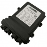
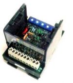
The 10 Universal Signal Input Module measures up to 10 analog inputs (0-5V, 0- | The 10 Universal Signal Input Module measures up to 10 analog inputs (0-5V, 0-20mA or 4-20mA) for connection to a variety of analog machine sensors or levers and sends the data to a CAN network. The user can also select multiple PWM or frequency inputs as well as a counter input. An active high digital input is another user-selectable input. | ||
{| class="wikitable" style="text-align: center;" cellpadding = "5" | {| class="wikitable" style="text-align: center;" cellpadding = "5" | ||
| Line 49: | Line 55: | ||
!scope="col"|Part Number | !scope="col"|Part Number | ||
!scope="col"|Webstore | !scope="col"|Webstore | ||
!scope="col"|More Information | !scope="col"|Downloads | ||
!scope="col" style = "width:180px;"|More Information | |||
|- style="vertical-align:middle;" | |- style="vertical-align:middle;" | ||
| Line 57: | Line 64: | ||
|- style="vertical-align:middle;" | |- style="vertical-align:middle;" | ||
|style = "height:125px; width:180px;"| | |style = "height:125px; width:180px;"| | ||
'''10 Universal Signal Input<br>CAN Controller'''<br> | '''10 Universal Signal Input<br>CAN Controller'''<br>SAE J1939 | ||
|style = "height:125px; width:180px;"| | |style = "height:125px; width:180px;"| | ||
AX030120<br> | AX030120<br> | ||
|style = "height:125px; width:180px;"| | |style = "height:125px; width:180px;"| | ||
'''[ | '''[https://store.neweagle.net/shop/products/input-output-devices/10-analog-input-module-sae-j1939-500kbps/ Purchase]''' | ||
|style = "height: | |style = "height:150px; width:180px;" rowspan="5"| | ||
'''[ | '''[[System_Input_Modules_Downloads#10_Universal_Signal_Input_to_CAN | Datasheets]]''' | ||
|style = "height:150px;" rowspan="5"| | |||
'''-''' | |||
|- style="vertical-align:middle;" | |- style="vertical-align:middle;" | ||
|style = "height:125px; width:180px;"| | |style = "height:125px; width:180px;"| | ||
'''10 Universal Signal Input<br>CAN Controller'''<br> | '''10 Universal Signal Input<br>CAN Controller'''<br>SAE J1939,<br>500 kbps | ||
|style = "height:125px; width:180px;"| | |style = "height:125px; width:180px;"| | ||
AX030120-01 | AX030120-01 | ||
|style = "height:125px; width:180px;"| | |style = "height:125px; width:180px;"| | ||
'''[ | '''Please contact [mailto:sales@neweagle.net sales]''' | ||
|- style="vertical-align:middle;" | |- style="vertical-align:middle;" | ||
|style = "height:125px; width:180px;"| | |style = "height:125px; width:180px;"| | ||
'''10 Universal Signal Input<br>CAN Controller'''<br> | '''10 Universal Signal Input<br>CAN Controller'''<br>SAE J1939,<br>1 Mbps | ||
|style = "height:125px; width:180px;"| | |style = "height:125px; width:180px;"| | ||
| Line 87: | Line 94: | ||
|style = "height:125px; width:180px;"| | |style = "height:125px; width:180px;"| | ||
'''Please contact [mailto:sales@neweagle.net sales]''' | '''Please contact [mailto:sales@neweagle.net sales]''' | ||
|- style="vertical-align:middle;" | |- style="vertical-align:middle;" | ||
|style = "height:125px; width:180px;"| | |style = "height:125px; width:180px;"| | ||
'''10 Universal Signal Input<br>CAN Controller'''<br> | '''10 Universal Signal Input<br>CAN Controller'''<br>CANOpen | ||
|style = "height:125px; width:180px;"| | |style = "height:125px; width:180px;"| | ||
| Line 99: | Line 103: | ||
|style = "height:125px; width:180px;"| | |style = "height:125px; width:180px;"| | ||
'''[ | '''[https://store.neweagle.net/shop/products/input-output-devices/10-analog-input-module-canopen/ Purchase]''' | ||
|} | |} | ||
===18 Digital | ===18 Digital Signal Input to CAN=== | ||
The 18 Digital Signal Input Module accepts up to 10 digital type inputs (active high/active low, PWM signal, | The 18 Digital Signal Input Module accepts up to 10 digital type inputs (active high/active low, PWM signal, frequency or counter). Eight additional digital inputs are user selectable as Active High or Active Low. The electronic control can be connected to a variety of machine switches, sensors, PWM signals, etc. It interfaces with the machine’s CAN network (SAE J1939). Standard embedded software is provided. Rugged packaging in addition to a wide-ranging power supply input section for 12V or 24VDC power suits applications in the harsh environment of mobile equipment with on-board battery power. All setpoints are user configurable using the Electronic Assistant. | ||
{| class="wikitable" style="text-align: center;" cellpadding = "5" | {| class="wikitable" style="text-align: center;" cellpadding = "5" | ||
| Line 116: | Line 117: | ||
!scope="col"|Part Number | !scope="col"|Part Number | ||
!scope="col"|Webstore | !scope="col"|Webstore | ||
!scope="col"|More Information | !scope="col" style = "width:180px;"|Downloads | ||
!scope="col" style = "width:180px;"|More Information | |||
|- style="vertical-align:middle;" | |||
|style = "height:150px; width:180px;" rowspan="5"| | |||
[[File:AX030310-01.PNG|180px]] | |||
|- style="vertical-align:middle;" | |- style="vertical-align:middle;" | ||
| Line 125: | Line 131: | ||
AX030310-01 | AX030310-01 | ||
|style = "height:125px; width:180px;"| | |style = "height:125px; width:180px;"| | ||
'''[https://store.neweagle.net/products | '''[https://store.neweagle.net/shop/products/input-output-devices/18-digital-inputs-sae-j1939-500-kbps/ Purchase]''' | ||
|style = "height: | |style = "height:150px; width:180px;" rowspan="5"| | ||
'''[ | '''[[System_Input_Modules_Downloads#18_Digital_inputs_Input_to_CAN | Datasheets]]''' | ||
|rowspan = "5"| | |||
'''-''' | |||
|- style="vertical-align:middle;" | |-style="vertical-align:middle;" | ||
|style = "height:125px; width:180px;"| | |style = "height:125px; width:180px;"| | ||
'''10 Universal Signal Input<br>CAN Controller'''<br>SAE J1939,<br>1 Mbps | '''10 Universal Signal Input<br>CAN Controller'''<br>SAE J1939,<br>1 Mbps | ||
| Line 138: | Line 147: | ||
|style = "height:125px; width:180px;"| | |style = "height:125px; width:180px;"| | ||
'''Please contact [mailto:sales@neweagle.net sales]''' | '''Please contact [mailto:sales@neweagle.net sales]''' | ||
|- style="vertical-align:middle;" | |- style="vertical-align:middle;" | ||
| Line 151: | Line 157: | ||
|style = "height:125px; width:180px;"| | |style = "height:125px; width:180px;"| | ||
'''Please contact [mailto:sales@neweagle.net sales]''' | '''Please contact [mailto:sales@neweagle.net sales]''' | ||
|} | |} | ||
===20 Channel Thermocouple Scanner=== | ===20-Channel Thermocouple Scanner=== | ||
The Thermocouple Scanner monitors up to 20 thermocouple channels and the temperature information is provided to the engine control system over J1939( | The Thermocouple Scanner monitors up to 20 thermocouple channels and the temperature information is provided to the engine control system over J1939 (AX185000) or CANopen (AX185001). The scanner can flag low temperature warnings, high temperature warnings or high temperature shutdowns to the engine control system. It will also detect and indicate open circuits on the sensor wires. Temperature is measured in °C, with a 0.001°C resolution. The scanner is available in CANopen or J1939 CAN communication standards. | ||
{| class="wikitable" style="text-align: center;" cellpadding = "5" | {| class="wikitable" style="text-align: center;" cellpadding = "5" | ||
| Line 166: | Line 169: | ||
!scope="col"|Part Number | !scope="col"|Part Number | ||
!scope="col"|Webstore | !scope="col"|Webstore | ||
!scope="col"|Downloads | |||
!scope="col"|More Information | !scope="col"|More Information | ||
| Line 174: | Line 178: | ||
|- style="vertical-align:middle;" | |- style="vertical-align:middle;" | ||
|style = "height:125px; width:180px;"| | |style = "height:125px; width:180px;"| | ||
'''Thermocouple Scanner'''<br>20 Thermocouple Channels<br>CAN | '''Thermocouple Scanner'''<br>20 Thermocouple Channels<br>CAN (SAE J1939) | ||
|style = "height:125px; width:180px;"| | |style = "height:125px; width:180px;"| | ||
AX185000 | |||
|style = "height:125px; width:180px;"| | |style = "height:125px; width:180px;"| | ||
'''[ | '''[https://store.neweagle.net/shop/products/input-output-devices/20-channel-thermocouple-module-sae-j1939// Purchase]''' | ||
|style = "height: | |style = "height:125px; width:180px;" rowspan="3"| | ||
'''[ | '''[[System_Input_Modules_Downloads#20_Channel_Thermocouple_Scanner|Datasheets]]''' | ||
|style = "width:180px;" rowspan="5"| | |||
'''-''' | |||
|- style="vertical-align:middle;" | |- style="vertical-align:middle;" | ||
| Line 190: | Line 197: | ||
|style = "height:125px; width:180px;"| | |style = "height:125px; width:180px;"| | ||
AX185001 | |||
|style = "height:125px; width:180px;"| | |style = "height:125px; width:180px;"| | ||
'''[ | '''[https://store.neweagle.net/shop/products/input-output-devices/20-channel-thermocouple-module-sae-j1939// Purchase]''' | ||
|} | |} | ||
===RTD Scanner=== | ===RTD Scanner=== | ||
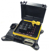
The RTD Scanner monitors up to | The RTD Scanner monitors up to eight channels of several types of RTDs. The temperature information is provided to an engine control system over an SAE J1939 or CANopen bus. Temperature information can include exhaust temperature, winding temperature and fluid temperature monitoring. All eight channels of temperature data are automatically sent over the CAN bus when power is applied with no additional programming or configuration required. Integral diagnostics determine RTD integrity and the RTD inputs are isolated from each other. The RTD temperature monitoring control features rugged packaging and watertight Deutsch IPD connectors. Applications include power generator sets. | ||
{| class="wikitable" style="text-align: center;" cellpadding = "5" | {| class="wikitable" style="text-align: center;" cellpadding = "5" | ||
| Line 208: | Line 212: | ||
!scope="col"|Part Number | !scope="col"|Part Number | ||
!scope="col"|Webstore | !scope="col"|Webstore | ||
!scope="col"|More Information | !scope="col"|Downloads | ||
!scope="col" style = "width:180px;"|More Information | |||
|- style="vertical-align:middle;" | |- style="vertical-align:middle;" | ||
| Line 216: | Line 221: | ||
|- style="vertical-align:middle;" | |- style="vertical-align:middle;" | ||
|style = "height:125px; width:180px;"| | |style = "height:125px; width:180px;"| | ||
'''RTD Scanner'''<br>CAN | '''RTD Scanner'''<br>CAN (SAE J1939) | ||
|style = "height:125px; width:180px;"| | |style = "height:125px; width:180px;"| | ||
| Line 224: | Line 229: | ||
'''Please contact [mailto:sales@neweagle.net sales]''' | '''Please contact [mailto:sales@neweagle.net sales]''' | ||
|style = "height: | |style = "height:125px; width:180px;" rowspan="3"| | ||
'''[ | '''[[System_Input_Modules_Downloads#RTD_Scanner|Datasheets]]''' | ||
|style = "width180px;" rowspan = "3"| | |||
'''-''' | |||
|- style="vertical-align:middle;" | |- style="vertical-align:middle;" | ||
| Line 235: | Line 243: | ||
|style = "height:125px; width:180px;"| | |style = "height:125px; width:180px;"| | ||
'''Please contact [mailto:sales@neweagle.net sales]''' | '''Please contact [mailto:sales@neweagle.net sales]''' | ||
|} | |} | ||
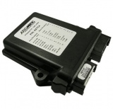
===4 Channel Thermocouple to CAN | ===4-Channel Thermocouple to CAN=== | ||
The Thermocouple Module monitors up to | The Thermocouple Module monitors up to four channels of Type J, K or T thermocouples (others on request). | ||
{| class="wikitable" style="text-align: center;" cellpadding = "5" | {| class="wikitable" style="text-align: center;" cellpadding = "5" | ||
| Line 250: | Line 255: | ||
!scope="col" style = "width:180px;"|Part Number | !scope="col" style = "width:180px;"|Part Number | ||
!scope="col" style = "width:180px;"|Webstore | !scope="col" style = "width:180px;"|Webstore | ||
!scope="col"|Downloads | |||
!scope="col" style = "width:180px;"|More Information | !scope="col" style = "width:180px;"|More Information | ||
|- | |- | ||
|[[File:AXTC4.jpg|160px]] | |[[File:AXTC4.jpg|160px]] | ||
|style = "height:150px; width:180px;"| | |style = "height:150px; width:180px;"| | ||
'''Thermocouple Module <br>4 Channel'''<br> CAN (SAE J1939)''' | '''Thermocouple Module <br>4-Channel'''<br> CAN (SAE J1939)''' | ||
|style = "height:150px; width:180px;"| | |style = "height:150px; width:180px;"| | ||
AXTC4 | AXTC4 | ||
|style = "height:150px; width:180px;"| | |style = "height:150px; width:180px;"| | ||
'''[ | '''[https://store.neweagle.net/shop/products/input-output-devices/4-channel-thermocouple-to-can-j1939/ Purchase]''' | ||
|style = "height:150px; width:180px;"| | |style = "height:150px; width:180px;"| | ||
'''[ | '''[[System_Input_Modules_Downloads#4_Channel_Thermocouple_to_CAN|Datasheets]]''' | ||
|style = "width:180px;"| | |||
'''-''' | |||
|} | |} | ||
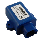
=== | ===Magnetic Pick-Up Sensor to CAN Converter (SAE J1939)=== | ||
{|style = | |||
Converts a magnetic speed sensor signal into SAE J1939 CAN messages for communication with control systems. | |||
{| class="wikitable" style="text-align: center;" cellpadding = "5" | {| class="wikitable" style="text-align: center;" cellpadding = "5" | ||
| Line 273: | Line 284: | ||
!scope="col" style = "width:180px;"|Part Number | !scope="col" style = "width:180px;"|Part Number | ||
!scope="col" style = "width:180px;"|Webstore | !scope="col" style = "width:180px;"|Webstore | ||
!scope="col"|Downloads | |||
!scope="col" style = "width:180px;"|More Information | !scope="col" style = "width:180px;"|More Information | ||
|- | |- | ||
|[[File: | |[[File:AX031500-636x608.png|150px]] | ||
|style = "height:150px; width:180px;"| | |style = "height:150px; width:180px;"| | ||
''' | '''Magnetic Pick-Up Sensor to CAN Converter''' | ||
|style = "height:150px; width:180px;"| | |style = "height:150px; width:180px;"| | ||
AX031500 | |||
|style = "height:150px; width:180px;"| | |style = "height:150px; width:180px;"| | ||
''' | '''[https://store.neweagle.net/shop/products/input-output-devices/magnetic-pick-up-can-converter-sae-j1939/ Purchase]''' | ||
|style = "height:150px; width:180px;"| | |style = "height:150px; width:180px;"| | ||
'''[ | '''[[System_Input_Modules_Downloads#Magnetic_Pick-Up_Sensor_to_CAN_Converter_.28SAE_J1939.29|Datasheet]]''' | ||
| | |||
'''-''' | |||
|} | |} | ||
=== | ===Isolated Signal Converter with CAN=== | ||
{|style = | {|style = | ||
The | A two-channel signal converter with isolation and CAN bus, this product is designed for diesel engine control systems, industrial automation, vehicle automation and machine control integration. The signal converter accepts two analog current or voltage signals, resistive or digital inputs, PWM or frequency/RPM inputs and converts them into two analog, PWM, frequency or digital signal outputs. A +5V reference powers sensor inputs. The unit has 4-way isolation between power, inputs, outputs and CAN. The I/O control includes CAN bus automation for SAE J1939 12VDC or 24VDC control systems or CANopen networks. It can be installed in control panels, industrial control automation systems, power generator set control systems, off-highway equipment, construction machines and test equipment. | ||
{| class="wikitable" style="text-align: center;" cellpadding = "5" | {| class="wikitable" style="text-align: center;" cellpadding = "5" | ||
| Line 297: | Line 311: | ||
!scope="col" style = "width:180px;"|Part Number | !scope="col" style = "width:180px;"|Part Number | ||
!scope="col" style = "width:180px;"|Webstore | !scope="col" style = "width:180px;"|Webstore | ||
!scope="col" style = "width:180px;"|Downloads | |||
!scope="col" style = "width:180px;"|More Information | !scope="col" style = "width:180px;"|More Information | ||
|- | |- | ||
|[[File: | |[[File:AX130510.png|150px]] | ||
|style = "height:150px; width:180px;"| | |style = "height:150px; width:180px;"| | ||
''' | '''Isolated Signal Converter with CAN'''<br>SAE J1939 | ||
|style = "height:150px; width:180px;"| | |style = "height:150px; width:180px;"| | ||
AX130510 | |||
|style = "height:150px; width:180px;"| | |style = "height:150px; width:180px;"| | ||
'''[ | '''[https://store.neweagle.net/shop/products/input-output-devices/isolated-signal-converter-with-can-sae-j1939/ Purchase]''' | ||
|style = "height:150px; width:180px;"| | |style = "height:150px; width:180px;"| | ||
'''[ | '''[[System_Input_Modules_Downloads#Isolated_Signal_Converter_with_CAN|Datasheet]]''' | ||
| | |||
'''-''' | |||
|} | |} | ||
=== | ===16 Analog I/O Module=== | ||
{|style = | {|style = | ||
The 16 Universal Signal Input/Analog Output CAN Controller can extend machine control networks by adding I/O to the CAN bus. This controller features one CAN port for user-defined communications over the bus. It accepts up to eight analog (0-5V, 0-10V, 0-20mA or 4-20mA) or digital or PWM frequency inputs and provides eight analog outputs (0-5V, 0-10V, +/-5V, +/-10V, 0-20mA, 4-20mA). Diagnostics messages are provided over the CAN network for the status of inputs or outputs. A RS-232 port is provided for user configuration via PC or for diagnostic purposes. | |||
{| class="wikitable" style="text-align: center;" cellpadding = "5" | {| class="wikitable" style="text-align: center;" cellpadding = "5" | ||
| Line 321: | Line 338: | ||
!scope="col" style = "width:180px;"|Part Number | !scope="col" style = "width:180px;"|Part Number | ||
!scope="col" style = "width:180px;"|Webstore | !scope="col" style = "width:180px;"|Webstore | ||
!scope="col" style = "width:180px;"|Downloads | |||
!scope="col" style = "width:180px;"|More Information | !scope="col" style = "width:180px;"|More Information | ||
|- | |- | ||
|[[File: | |[[File:AX030200.gif|150px]] | ||
|style = "height:150px; width:180px;"| | |||
'''16 Analog I/O Module'''<br>SAE J1939 | |||
|style = "height:150px; width:180px;"| | |||
AX030200 | |||
|style = "height:150px; width:180px;"| | |||
'''[https://store.neweagle.net/shop/products/input-output-devices/8-universal-signal-inputs-8-analog-outputs-sae-j1939/ Purchase]''' | |||
|style = "height:150px; width:180px;" rowspan="3"| | |||
'''[[System_Input_Modules_Downloads#16_Analog_I.2FO_Module|Datasheets]]''' | |||
|rowspan = "3"| | |||
'''-''' | |||
|- | |||
|[[File:AX030201.gif|150px]] | |||
|style = "height:150px; width:180px;"| | |style = "height:150px; width:180px;"| | ||
''' | '''16 Analog I/O Module'''<br>CANopen | ||
|style = "height:150px; width:180px;"| | |style = "height:150px; width:180px;"| | ||
AX030201 | |||
|style = "height:150px; width:180px;"| | |style = "height:150px; width:180px;"| | ||
'''Please contact [mailto:sales@neweagle.net sales]''' | '''Please contact [mailto:sales@neweagle.net sales]''' | ||
|} | |} | ||
=== | ===4-Channel Strain Gauge to CAN Controller=== | ||
The | The 4-Channel Strain Gauge CAN controller accepts up to four 4-wire strain gauge connections. The input range is user selectable from +/- 19.5mV to +/- 2.5VDC. It interfaces with the machine’s CAN network (SAE J1939). The measurement rate is 2.5 scans per second and the update rate is 400ms for all four channels. Standard embedded software is provided. Rugged IP67 rated packaging and a power supply input of 12VDC or 24VDC nominal suits applications in the harsh environment of mobile equipment with on-board battery power. All setpoints are user configurable using the Electronic Assistant. | ||
{| class="wikitable" style="text-align: center;" cellpadding = "5" | {| class="wikitable" style="text-align: center;" cellpadding = "5" | ||
!scope="col" style = "width:180px;"|Picture | !scope="col" style = "width:180px;"|Picture | ||
| Line 345: | Line 373: | ||
!scope="col" style = "width:180px;"|Part Number | !scope="col" style = "width:180px;"|Part Number | ||
!scope="col" style = "width:180px;"|Webstore | !scope="col" style = "width:180px;"|Webstore | ||
!scope="col" style = "width:180px;"|Downloads | |||
!scope="col" style = "width:180px;"|More Information | !scope="col" style = "width:180px;"|More Information | ||
|- | |- | ||
|[[File: | |[[File:AX200000.png|150px]] | ||
|style = "height: | |||
''' | |style = "height:160px;"| | ||
|style = "height:150px; width:180px;"| | '''4-Channel Strain Gauge to CAN Controller'''<br>SAE J1939 | ||
|style = "height:150px; | |style = "height:150px;"| | ||
'''[https://store.neweagle.net/products | AX200000 | ||
|style = "height:150px | |||
'''[ | |style = "height:150px;"| | ||
'''Please contact [mailto:sales@neweagle.net sales]''' | |||
|style = "height:150px;"| | |||
'''[[Other_IO_Devices_Downloads#4_Channel_Strain_Gauge_to_CAN_Controller | Datasheet]]''' | |||
| | |||
'''-''' | |||
|} | |||
===Connector Amplifier for Proportional Valves – DIN 43650A=== | |||
(0-10V input, 1.2A output, 2m grey cable, IP65) | |||
The connector amplifier supplies a solenoid valve with current proportional to an input control (0-10VDC or 0-20mA). Application: Accurate control of hydraulic and pneumatic proportional solenoid valves used in mobile construction equipment and industrial processes. | |||
{| class="wikitable" style="text-align: center;" cellpadding = "5" | |||
!scope="col" style = "width:180px;"|Picture | |||
!scope="col" style = "width:180px;"|Product Name | |||
!scope="col" style = "width:200px;"|Part Number | |||
!scope="col" style = "width:180px;"|Webstore | |||
!scope="col" style = "width:180px;"|Downloads | |||
!scope="col" style = "width:180px;"|More Information | |||
|- | |||
|[[File:Admin-ajax (002).jpg|150px]] | |||
|style = "height:160px;"| | |||
'''Connector Amplifier <br>for Proportional Valves<br> DIN 43650A''' | |||
|style = "height:150px;"| | |||
AX-CAPV-H-10V-1.2A-6C-2M | |||
|style = "height:150px;"| | |||
'''[https://store.neweagle.net/shop/products/input-output-devices/connector-amplifier-for-proportional-valves-10v-din-43650a/ Purchase]''' | |||
|style = "height:150px;"| | |||
'''[https://wiki.neweagle.net/ProductDocumentation/Input_Output_Devices/System_Input_Modules/TD1108AX_DataSheet.pdf Datasheet]''' | |||
| | |||
'''-''' | |||
|} | |} | ||
=== | ===GPS Receiver - CAN J1939=== | ||
The | The GPS Receiver – J1939 is a fast update GPS that outputs J1939 data. Its update time is only 0.1 seconds, and it is extremely accurate at capturing position, velocity and time. | ||
{| class="wikitable" style="text-align: center;" cellpadding = "5" | {| class="wikitable" style="text-align: center;" cellpadding = "5" | ||
| Line 369: | Line 434: | ||
!scope="col" style = "width:180px;"|Part Number | !scope="col" style = "width:180px;"|Part Number | ||
!scope="col" style = "width:180px;"|Webstore | !scope="col" style = "width:180px;"|Webstore | ||
!scope="col" style = "width:180px;"|Downloads | |||
!scope="col" style = "width:180px;"|More Information | !scope="col" style = "width:180px;"|More Information | ||
|- | |- | ||
|[[File: | |[[File:GPS Reciever.jpg|150px]] | ||
|style = "height:150px; width:180px;"| | |||
'''GPS Receiver CAN J1939 - 250 Baud'''<br> | |||
|style = "height:150px; width:180px;"| | |||
GPS-REC-J1939-001 | |||
|style = "height:150px; width:180px;"| | |style = "height:150px; width:180px;"| | ||
''' | '''[https://store.neweagle.net/shop/products/displays-gauges/gauges-displays-gauges/gps-receiver-can-j1939/ Purchase]''' | ||
|style = "height:150px; width:180px;" rowspan="3"| | |||
'''[https://wiki.neweagle.net/ProductDocumentation/Input_Output_Devices/System_Input_Modules/GPS-REC-J1939_DataSheet.pdf Datasheet]''' | |||
|rowspan = "3"| | |||
'''-''' | |||
|- | |||
|[[File:GPS Reciever.jpg|150px]] | |||
|style = "height:150px; width:180px;"| | |style = "height:150px; width:180px;"| | ||
'''GPS Receiver CAN J1939 - 500 Baud'''<br> | |||
|style = "height:150px; width:180px;"| | |style = "height:150px; width:180px;"| | ||
GPS-REC-J1939-002 | |||
|style = "height:150px; width:180px;"| | |style = "height:150px; width:180px;"| | ||
'''[ | '''[https://store.neweagle.net/shop/products/displays-gauges/gauges-displays-gauges/gps-receiver-can-j1939-500-baud/ Purchase]''' | ||
|} | |} | ||
| Line 386: | Line 463: | ||
===CM0410 Input Output Module=== | ===CM0410 Input Output Module=== | ||
The CM0410 is a general purpose input / output controller that includes a single J1939 CAN interface, | The CM0410 is a general-purpose input/output controller that includes a single J1939 CAN interface, four inputs, one high-side current measurement pass-through and 10 high-side outputs. The main function of the product is to provide a means of controlling relays through J1939 messages on the CAN bus. The CM0410 is a CAN slave module only and supports no standalone operation. | ||
{| class="wikitable" style="text-align: center;" cellpadding = "5" | {| class="wikitable" style="text-align: center;" cellpadding = "5" | ||
| Line 394: | Line 471: | ||
!scope="col" style = "width:180px;"|Part Number | !scope="col" style = "width:180px;"|Part Number | ||
!scope="col" style = "width:180px;"|Webstore | !scope="col" style = "width:180px;"|Webstore | ||
!scope="col" style = "width:180px;"|Downloads | |||
!scope="col" style = "width:180px;"|More Information | !scope="col" style = "width:180px;"|More Information | ||
|- | |- | ||
| Line 402: | Line 480: | ||
CM0410 | CM0410 | ||
|style = "height:150px; width:180px;"| | |style = "height:150px; width:180px;"| | ||
'''[ | '''[https://store.neweagle.net/shop/products/input-output-devices/slave-can-module-j1939/ Purchase]''' | ||
| | |||
'''-''' | |||
|style = "height:150px; width:180px;"| | |style = "height:150px; width:180px;"| | ||
'''[ | '''[[CM0410|More Details]]''' | ||
|} | |} | ||
| Line 417: | Line 495: | ||
!scope="col" style = "width:180px;"|Part Number | !scope="col" style = "width:180px;"|Part Number | ||
!scope="col" style = "width:180px;"|Webstore | !scope="col" style = "width:180px;"|Webstore | ||
!scope="col" style = "width:180px;"|Downloads | |||
!scope="col" style = "width:180px;"|More Information | !scope="col" style = "width:180px;"|More Information | ||
|- | |- | ||
| Line 425: | Line 504: | ||
AX030520 | AX030520 | ||
|style = "height:150px; width:180px;"| | |style = "height:150px; width:180px;"| | ||
''' | '''[https://store.neweagle.net/shop/products/input-output-devices/can-to-1-analog-signal-output-sae-j1939/ Purchase]''' | ||
|style = "height:150px; width:180px;"| | |style = "height:150px; width:180px;" rowspan = "3"| | ||
'''[ | '''[[System_Output_Modules_Downloads#CAN_Analog_Signal_Output_Controllers|Datasheets]]''' | ||
| | |rowspan = "3"| | ||
'''-''' | |||
|- | |- | ||
|[[File:AX030520.gif|180px]] | |[[File:AX030520.gif|180px]] | ||
| Line 444: | Line 517: | ||
AX030521 | AX030521 | ||
|style = "height:150px; width:180px;"| | |style = "height:150px; width:180px;"| | ||
''' | '''[https://store.neweagle.net/shop/products/input-output-devices/can-to-1-analog-signal-output-canopen/ Purchase]''' | ||
|} | |} | ||
| Line 457: | Line 528: | ||
!scope="col" style = "width:180px;"|Part Number | !scope="col" style = "width:180px;"|Part Number | ||
!scope="col" style = "width:180px;"|Webstore | !scope="col" style = "width:180px;"|Webstore | ||
!scope="col" style = "width:180px;"|Downloads | |||
!scope="col" style = "width:180px;"|More Information | !scope="col" style = "width:180px;"|More Information | ||
|- | |- | ||
| Line 465: | Line 537: | ||
AX031200 | AX031200 | ||
|style = "height:150px; width:180px;"| | |style = "height:150px; width:180px;"| | ||
'''[https://store.neweagle.net/11-9-can-controller-sae-j1939 | '''[https://store.neweagle.net/shop/products/input-output-devices/11-9-can-controller-sae-j1939/ Purchase]''' | ||
|style = "height:150px; width:180px;"| | |style = "height:150px; width:180px;" rowspan = "3"| | ||
'''[ | '''[[System_Output_Modules_Downloads#11:9_CAN_Controllers | Datasheets]]''' | ||
| | |rowspan = "3"| | ||
'''-''' | |||
|- | |- | ||
|[[File:AX0312001.gif|180px]] | |[[File:AX0312001.gif|180px]] | ||
| Line 484: | Line 550: | ||
AX031201 | AX031201 | ||
|style = "height:150px; width:180px;"| | |style = "height:150px; width:180px;"| | ||
'''[https://store.neweagle.net/products | '''[https://store.neweagle.net/shop/products/input-output-devices/11-9-can-controller-canopen/ Purchase]''' | ||
|} | |} | ||
===CAN to 10 Output Valve Controller=== | ===CAN to 10 Output Valve Controller=== | ||
Available in | Available in 12V, 24V and 48V operating input power modules, this durable CAN-controlled output controller is capable of providing 10 universal outputs at up to 2.5A or 7A for the whole module. Applications include proportional valves, hotshot control profiles, PWM signals and on/off valves. Settings may be user configured via Windows-based Electronic Assistant. | ||
{| class="wikitable" style="text-align: center;" cellpadding = "5" | {| class="wikitable" style="text-align: center;" cellpadding = "5" | ||
| Line 498: | Line 562: | ||
!scope="col"|Part Number | !scope="col"|Part Number | ||
!scope="col"|Webstore | !scope="col"|Webstore | ||
!scope="col"|More Information | !scope="col"|Downloads | ||
!scope="col" style = "width:180px;"|More Information | |||
|- style="vertical-align:middle;" | |- style="vertical-align:middle;" | ||
| Line 511: | Line 576: | ||
AX021210 | AX021210 | ||
|style = "height:115px; width:180px;"| | |style = "height:115px; width:180px;"| | ||
'''[ | '''Please contact [mailto:sales@neweagle.net sales]''' | ||
|style = "height:115px; width:180px;"| | |style = "height:115px; width:180px;" rowspan="4"| | ||
'''[ | '''[[System_Output_Modules_Downloads#CAN_to_10_Output_Valve_Controller|Datasheets]]''' | ||
|rowspan = "4"| | |||
'''-''' | |||
|- style="vertical-align:middle;" | |- style="vertical-align:middle;" | ||
| Line 523: | Line 591: | ||
AX021210-01 | AX021210-01 | ||
|style = "height:115px; width:180px;"| | |style = "height:115px; width:180px;"| | ||
'''[ | '''[https://store.neweagle.net/shop/products/input-output-devices/can-to-10-output-valve-controller-j1939-500kbps/ Purchase]''' | ||
|- style="vertical-align:middle;" | |- style="vertical-align:middle;" | ||
| Line 536: | Line 601: | ||
|style = "height:115px; width:180px;"| | |style = "height:115px; width:180px;"| | ||
'''[ | '''[https://store.neweagle.net/shop/products/input-output-devices/can-to-10-output-valve-controller-canopen/ Purchase]''' | ||
|} | |} | ||
===CAN (J1939) to 4 Channel Analog Output=== | ===CAN (J1939) to 4-Channel Analog Output=== | ||
The IO device belongs to a family of Axiomatic smart controllers with programmable internal architecture. This provides users with flexibility, allowing them to build their own custom controller with a required functionality from a set of predefined internal functional blocks using the PC-based Axiomatic Electronic | The IO device belongs to a family of Axiomatic smart controllers with programmable internal architecture. This provides users with flexibility, allowing them to build their own custom controller with a required functionality from a set of predefined internal functional blocks using the PC-based Axiomatic Electronic Assistant software tool. Application programming is performed through the CAN interface, without disconnecting the controller from the user’s system. | ||
{| class="wikitable" style="text-align: center;" cellpadding = "5" | {| class="wikitable" style="text-align: center;" cellpadding = "5" | ||
| Line 553: | Line 615: | ||
!scope="col" style = "width:180px;"|Part Number | !scope="col" style = "width:180px;"|Part Number | ||
!scope="col" style = "width:180px;"|Webstore | !scope="col" style = "width:180px;"|Webstore | ||
!scope="col" style = "width:180px;"|Downloads | |||
!scope="col" style = "width:180px;"|More Information | !scope="col" style = "width:180px;"|More Information | ||
|- | |- | ||
| Line 558: | Line 621: | ||
|style = "height:160px;"| | |style = "height:160px;"| | ||
'''CAN to 4 Channel <br>Analog Output Device'''<br>250 kbps <br>(SAE J1939) | '''CAN to 4-Channel <br>Analog Output Device'''<br>250 kbps <br>(SAE J1939) | ||
|style = "height:150px;"| | |style = "height:150px;"| | ||
| Line 564: | Line 627: | ||
|style = "height:150px;"| | |style = "height:150px;"| | ||
'''[ | '''[https://store.neweagle.net/shop/products/input-output-devices/can-to-4-analog-output-controller-sae-j1939-250-kbps/ Purchase]''' | ||
|style = "height:150px;"| | |style = "height:150px;" rowspan = "3"| | ||
'''[ | '''[[System_Output_Modules_Downloads#CAN_.28J1939.29_to_4_Channel_Analog_Output|Datasheets]]''' | ||
| | |rowspan = "3"| | ||
'''-''' | |||
|- | |- | ||
|[[File:4 Analog Signal Outputs CAN Controller with Electronic Assistant.jpg|150px]] | |[[File:4 Analog Signal Outputs CAN Controller with Electronic Assistant.jpg|150px]] | ||
| Line 588: | Line 644: | ||
|style = "height:150px;"| | |style = "height:150px;"| | ||
'''Please contact [mailto:sales@neweagle.net sales]''' | '''Please contact [mailto:sales@neweagle.net sales]''' | ||
|} | |} | ||
===CANopen to 4 Channel Analog Outputs=== | ===CANopen to 4-Channel Analog Outputs=== | ||
The 4 Analog Signal Outputs CAN IO device belongs to a family of Axiomatic user-customizable smart controllers. The programmable internal architecture provides users with an ultimate flexibility, allowing them to build their own custom controller with a required functionality from a set of predefined internal functional blocks using any commercially available | The 4-Channel Analog Signal Outputs CAN IO device belongs to a family of Axiomatic user-customizable smart controllers. The programmable internal architecture provides users with an ultimate flexibility, allowing them to build their own custom controller with a required functionality from a set of predefined internal functional blocks using any commercially available CANopen tools. | ||
{| class="wikitable" style="text-align: center;" cellpadding = "5" | {| class="wikitable" style="text-align: center;" cellpadding = "5" | ||
| Line 603: | Line 656: | ||
!scope="col" style = "width:180px;"|Part Number | !scope="col" style = "width:180px;"|Part Number | ||
!scope="col" style = "width:180px;"|Webstore | !scope="col" style = "width:180px;"|Webstore | ||
!scope="col" style = "width:180px;"|Downloads | |||
!scope="col" style = "width:180px;"|More Information | !scope="col" style = "width:180px;"|More Information | ||
|- | |- | ||
| Line 608: | Line 662: | ||
[[File:4_Analog_Signal_Outputs_with_CANopen_Controller.jpg|120px]] | [[File:4_Analog_Signal_Outputs_with_CANopen_Controller.jpg|120px]] | ||
|'''CANopen to 4 Analog | |'''CANopen to 4-Channel Analog Signal Outputs Device''' | ||
|style = "height:150px; width:180px;"| | |style = "height:150px; width:180px;"| | ||
AX030501 | AX030501 | ||
|style = "height:150px; width:180px;"| | |style = "height:150px; width:180px;"| | ||
'''[ | '''[https://store.neweagle.net/shop/products/input-output-devices/can-to-4-analog-output-controller-canopen/ Purchase]''' | ||
|style = "height:150px; width:180px;"| | |style = "height:150px; width:180px;"| | ||
'''[ | '''[[System_Output_Modules_Downloads#CANopen_to_4_Channel_Analog_Outputs|Datasheet]]''' | ||
| | |||
'''-''' | |||
|} | |} | ||
===TC/Analog Input of CAN Controller=== | ===TC/Analog Input of CAN Controller=== | ||
The TC/Analog Inputs to CAN Controller receives inputs from engine coolant, fuel and differential pressure sensors, engine temperature sensors, thermistors as well as thermocouples and is networked to | The TC/Analog Inputs to CAN Controller receives inputs from engine coolant, fuel and differential pressure sensors, engine temperature sensors, thermistors as well as thermocouples and is networked to an SAE J1939 based control system. Seven +5V references (10mA) are provided to power the sensors. The two CAN ports are isolated from signal inputs and thermocouple inputs. | ||
{| class="wikitable" style="text-align: center;" cellpadding = "5" | {| class="wikitable" style="text-align: center;" cellpadding = "5" | ||
| Line 627: | Line 683: | ||
!scope="col" style = "width:180px;"|Part Number | !scope="col" style = "width:180px;"|Part Number | ||
!scope="col" style = "width:180px;"|Webstore | !scope="col" style = "width:180px;"|Webstore | ||
!scope="col" style = "width:180px;"|Downloads | |||
!scope="col" style = "width:180px;"|More Information | !scope="col" style = "width:180px;"|More Information | ||
|- | |- | ||
| Line 633: | Line 690: | ||
|'''TC/Analog Input of CAN Controller''' | |'''TC/Analog Input of CAN Controller''' | ||
|style = "height:130px; width:180px;"| | |style = "height:130px; width:180px;"| | ||
AX181000 | |||
|style = "height:130px; width:180px;"| | |style = "height:130px; width:180px;"| | ||
'''[ | '''[https://store.neweagle.net/shop/products/input-output-devices/tc-analog-input-to-can-controller/ Purchase]''' | ||
|style = "height:130px; width:180px;"| | |style = "height:130px; width:180px;"| | ||
'''[ | '''[[System_Output_Modules_Downloads#Thermocouple.2FAnalog_Input_of_CAN_Controller | Datasheet]]''' | ||
|'''-''' | |||
|- style = "height:50px; width:180px;" rowspan="2"| | |- style = "height:50px; width:180px;" rowspan="2"| | ||
|Connector Kit | |'''Connector Kit''' | ||
|style = "height:50px; width:180px;"| | |style = "height:50px; width:180px;"| | ||
AX070123 | AX070123 | ||
|style = "height:50px; width:180px;"| | |style = "height:50px; width:180px;"| | ||
'''[ | '''Please contact [mailto:sales@neweagle.net sales]''' | ||
|style = "height:50px; width:180px;"| | |style = "height:50px; width:180px;"| | ||
-- | '''-''' | ||
|'''-''' | |||
|} | |} | ||
===CAN Enabled Current Driver=== | ===CAN Enabled Current Driver=== | ||
The Single 5 amp bi-directional current driver is built from either a MotoHawk ECM S12-24 or ECM 563-48 ECU. | The Single 5-amp bi-directional current driver is built from either a MotoHawk ECM S12-24 or ECM 563-48 ECU. This is a customizable solution that allows for custom logic or the use as a simple CAN-based slave. Configuration and service tools are available. | ||
{| class="wikitable" style="text-align: center;" cellpadding = "5" | {| class="wikitable" style="text-align: center;" cellpadding = "5" | ||
| Line 660: | Line 719: | ||
!scope="col"|Part Number | !scope="col"|Part Number | ||
!scope="col"|Webstore | !scope="col"|Webstore | ||
!scope="col" style = "width:180px;"|Downloads | |||
!scope="col"|More Information | !scope="col"|More Information | ||
|- | |- | ||
| Line 669: | Line 729: | ||
|style = "height:180px; width:180px;"| | |style = "height:180px; width:180px;"| | ||
''(Custom)''<br>Please contact [mailto:sales@neweagle.net sales] | ''(Custom)''<br>'''Please contact [mailto:sales@neweagle.net sales] | ||
|style = "height:180px; width:180px;"| | |style = "height:180px; width:180px;"| | ||
Built upon the | Built upon the | ||
<br>'''[ | <br>'''[[Controllers#ECM-S12-24_.28SECM24.29| ECM-S12-24]]''' <br>or the <br>'''[[Controllers#ECM-563-48_.28ECM48.29| ECM-563-48]]''' | ||
|style = "height:180px; width:180px;"| | |style = "height:180px; width:180px;"| | ||
-- | '''-''' | ||
|style = "width:180px;"| | |||
'''-''' | |||
|} | |} | ||
===Multiplexed Power Distribution Module (MPDM)=== | ===Multiplexed Power Distribution Module (MPDM)=== | ||
The New | The New Eagle Multiplexed Power Distribution Module offers economical CAN Network oversight for high power circuits in vehicle power distribution. Manufactured as a hardened and weather tight module, it may be configured to provide various OEM circuit protection and switching functions using industry standard fuses, relays and breakers, with the status and control of each circuit accessible through J1939/CANopen messages. | ||
{{MPDM-NE1}} | {{MPDM-NE1}} | ||
=== | ===DC-DC Converter=== | ||
{{AX081530}} | {{AX081530}} | ||
===High Current H-Bridge Module=== | |||
{{HB-30A}} | |||
===CAN Enabled Current Driver=== | |||
The Single 5-amp bi-directional current driver is built from either a MotoHawk ECM S12-24 or ECM 563-48 ECU. This is a customizable solution that allows for custom logic or the use as a simple CAN-based slave. Configuration and service tools are available. | |||
{| class="wikitable" style="text-align: center;" cellpadding = "5" | |||
!scope="col" style = "width:180px;"|Picture | |||
!scope="col"|Product Name | |||
!scope="col"|Part Number | |||
!scope="col"|Webstore | |||
!scope="col"|Downloads | |||
!scope="col" style = "width:180px;"|More Information | |||
|- | |||
|style = "height:180px; width:180px;"| | |||
[[file:AX-RSD-DR-4-20MA-2A.jpg|150px]] | |||
|style = "height:180px; width:180px;"| | |||
'''Remote Mount Solenoid Driver – DIN Rail Mount''' | |||
|style = "height:180px; width:180px;"| | |||
'''AX-RSD-DR-4-20MA-2A | |||
|style = "height:180px; width:180px;"| | |||
'''[https://store.neweagle.net/shop/products/input-output-devices/remote-mount-solenoid-driver-din-rail-mount/ Purchase] | |||
|style = "height:180px; width:180px;"| | |||
'''[https://www.axiomatic.com/4-20ma-remote-driver.pdf Datasheet] | |||
|'''-''' | |||
|} | |||
==Protocol Converters== | ==Protocol Converters== | ||
| Line 695: | Line 788: | ||
!scope="col" style = "width:180px;"|Part Number | !scope="col" style = "width:180px;"|Part Number | ||
!scope="col" style = "width:180px;"|Webstore | !scope="col" style = "width:180px;"|Webstore | ||
!scope="col" style = "width:180px;"|Downloads | |||
!scope="col" style = "width:180px;"|More Information | !scope="col" style = "width:180px;"|More Information | ||
|- | |- | ||
| Line 703: | Line 797: | ||
AX140400 | AX140400 | ||
|style = "height:150px; width:180px;"| | |style = "height:150px; width:180px;"| | ||
'''[https://store.neweagle.net/products | '''[https://store.neweagle.net/shop/products/input-output-devices/protocol-converter-j1587-to-j1939-gateway/ Purchase]''' | ||
|style = "height:150px; width:180px;"| | |style = "height:150px; width:180px;"| | ||
'''[ | '''[[Other_IO_Devices_Downloads#2_SAE_J1939.2C_SAE_J1587 | Datasheet]]''' | ||
|'''-''' | |||
|} | |} | ||
== | ===LIN to CAN Protocol Converter=== | ||
{| | |||
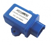
The LIN-CAN Protocol Converter, SAE J1939 exchanges data between a LIN network and a CAN network. This device is J1939 compliant and can be configured with the Axiomatic Electronic Assistant PC tool. | |||
=== | {| class="wikitable" style="text-align: center;" cellpadding = "5" | ||
!scope="col" style = "width:180px;"|Picture | |||
!scope="col" style = "width:180px;"|Product Name | |||
!scope="col" style = "width:180px;"|Part Number | |||
!scope="col" style = "width:180px;"|Webstore | |||
!scope="col" style = "width:180px;"|Downloads | |||
!scope="col" style = "width:180px;"|More Information | |||
|- | |||
!scope="col"| | |[[File:AX140600.jpg|180px]] | ||
!scope="col"| | |style = "height:150px; width:180px;"| | ||
!scope="col"| | '''LIN-CAN Protocol Converter, SAE J1939, Extended, <br>Auto-baud-rate-detect | ||
!scope="col"| | |style = "height:150px; width:180px;"| | ||
!scope="col"|More Information | AX140600-03 | ||
|style = "height:150px; width:180px;"| | |||
'''[https://store.neweagle.net/shop/products/input-output-devices/lin-can-protocol-converter-sae-j1939-extended-auto-baud-rate-detect/ Purchase] ''' | |||
|style = "height:150px; width:180px;"| | |||
'''[[System_Input_Modules_Downloads#LIN_to_CAN_Protocol_Converter | Datasheet]]''' | |||
|'''-''' | |||
|- | |- | ||
| | |[[File:AX140600.jpg|180px]] | ||
[[ | |style = "height:150px; width:180px;"| | ||
'''LIN-CAN Protocol Converter, SAE J1939, 500kbps Baud Rate | |||
|style = "height: | |style = "height:150px; width:180px;"| | ||
''' | AX140600-01 | ||
|style = "height:150px; width:180px;"| | |||
|style = "height: | '''[https://store.neweagle.net/shop/products/input-output-devices/lin-can-protocol-converter-sae-j1939/ Purchase] ''' | ||
|style = "height:150px; width:180px;"| | |||
'''[[System_Input_Modules_Downloads#LIN_to_CAN_Protocol_Converter | Datasheet]]''' | |||
|style = "height: | |'''-''' | ||
'''[ | |||
|style = "height: | |||
'''[ | |||
|} | |} | ||
==Digital Keypads== | ==Digital Keypads== | ||
==== | ====4-Position Keypad==== | ||
Hassle-free control and customization is literally at your fingertips. The Power Key is reconfigurable, readdressable and relegendable, requiring only a laptop or PC connection. Its secure-locking inserts (not included in purchase) can be interchanged to match the configuration. | Hassle-free control and customization is literally at your fingertips. The Power Key is reconfigurable, readdressable and relegendable, requiring only a laptop or PC connection. Its secure-locking inserts (not included in purchase) can be interchanged to match the configuration. | ||
{{PKP-2200-100}} | {{PKP-2200-100}} | ||
==== | ====8-Position Keypad==== | ||
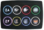
This standard keypad allows a designer to build a semi-custom system for a minimal cost. Each keypad is made from extremely high-quality and rugged silicone that can be laser etched with specified button legends, text or company logos. Communication protocols include RS485, J1030/J1939-11, CANopen and others. | This standard keypad allows a designer to build a semi-custom system for a minimal cost. Each keypad is made from extremely high-quality and rugged silicone that can be laser etched with specified button legends, text or company logos. Communication protocols include RS485, J1030/J1939-11, CANopen and others. | ||
{{KEYPAD-DS-008-00}} | {{KEYPAD-DS-008-00}} | ||
''Note: CAN DBC file available upon request.'' | |||
<!-- This is a comment | <!-- This is a comment | ||
<span style="color:#8B0000">'''Keyless Ignition Keypad'''</span> | <span style="color:#8B0000">'''Keyless Ignition Keypad'''</span> | ||
| Line 772: | Line 862: | ||
!scope="col"|Part Number | !scope="col"|Part Number | ||
!scope="col"|Picture | !scope="col"|Picture | ||
!scope="col"| | !scope="col"|Webstore | ||
!scope="col"|More Information | !scope="col"|More Information | ||
|- | |- | ||
| Line 788: | Line 878: | ||
==Specialty IO Modules== | ==Specialty IO Modules== | ||
===J1772 Vehicle Power Interface Module (VPIM)=== | ===J1772 Vehicle Power Interface Module (VPIM)=== | ||
| Line 823: | Line 886: | ||
===PWM to Analog Converter (Pedal Emulator)=== | ===PWM to Analog Converter (Pedal Emulator)=== | ||
The New Eagle PWM to Analog Converter converts | The New Eagle PWM to Analog Converter converts three separate channels of PWM signals to proportional 0-5V analog signals. The converter is especially useful when paired with control modules with PWM outputs, but no 0-5V analog outputs. This device is very useful as a pedal emulator. | ||
converter is especially useful when paired with control modules with PWM outputs, but no 0-5V analog outputs. This device is very useful as a pedal emulator. | |||
{| class="wikitable" style="text-align: center;" cellpadding = "5" | {| class="wikitable" style="text-align: center;" cellpadding = "5" | ||
!scope="col"|Picture | !scope="col"|Picture | ||
!scope="col"|Part Number | |||
!scope="col"|Part Number | |||
!scope="col"|Webstore | !scope="col"|Webstore | ||
!scope="col"|Downloads | |||
!scope="col"|More Information | !scope="col"|More Information | ||
|- | |- | ||
| Line 836: | Line 898: | ||
[[image:PWM-AN-024-1403.PNG|150px]] | [[image:PWM-AN-024-1403.PNG|150px]] | ||
|style = "height:180px; width:180px;"| | |style = "height:180px; width:180px;"| | ||
PWM-AN-024-1403 | |||
|style = "height:180px; width:180px;"| | |style = "height:180px; width:180px;"| | ||
'''[https://store.neweagle.net/shop/our-markets/electric-hybrid/lv-accessories/pwm-to-analog-converter-w-24-pin-header/ Purchase]''' | |||
|style = "height:180px; width:180px;"| | |style = "height:180px; width:180px;"| | ||
'''[ | '''[[PWM to Analog Converter#Datasheet|Downloads]]''' | ||
|style = "height:180px; width:180px;"| | |style = "height:180px; width:180px;"| | ||
'''[[PWM to Analog Converter|More Details]]''' | '''[[PWM to Analog Converter|More Details]]''' | ||
|} | |} | ||
The | ===DBW PWM to Analog Pedal Emulator=== | ||
The New Eagle DBW PWM to Analog Converter is optimized to operate in Drive-By-Wire (DBW) applications. It is designed to take the Raw Analog and Digital signals from the accelerator and brake pedals respectively and either pass the signal through to the OEM ECU or override the signals with commanded PWM signals from the DBW Aftermarket ECU. | |||
{| class="wikitable" style="text-align: center;" cellpadding = "5" | {| class="wikitable" style="text-align: center;" cellpadding = "5" | ||
!scope="col"|Picture | !scope="col"|Picture | ||
!scope="col"| | !scope="col"|Part Number | ||
!scope="col"|Webstore | |||
!scope="col"|Downloads | |||
!scope="col"|More Information | |||
|- | |||
|style = "height:180px; width:180px;" rowspan="2"| | |||
[[image:PWM-AN-024-1403.PNG|150px]] | |||
|style = "height:90px; width:180px;"| | |||
PWM-DBW-024-2001 | |||
|style = "height:180px; width:180px;" rowspan="2"| | |||
'''Please contact [mailto:sales@neweagle.net sales]''' | |||
|style = "height:90px; width:180px;"| | |||
'''[https://wiki.neweagle.net/ProductDocumentation/Input_Output_Devices/Specialty_IO_Modules/PWM-DBW-024-2001_DataSheet.pdf Datasheet]''' | |||
|style = "height:180px; width:180px;" rowspan="2"| | |||
'''[[DBW_PWM_to_Analog_Pedal_Emulator|More Details]]''' | |||
|- | |||
|style = "height:90px;"| | |||
PWM-DBW-024-2002 | |||
|style = "height:90px;"| | |||
'''[https://wiki.neweagle.net/ProductDocumentation/Input_Output_Devices/Specialty_IO_Modules/PWM-DBW-024-2002_DataSheet.pdf Datasheet]''' | |||
|} | |||
=== LVDT Simulator for LVDT or RVDT Sensors === | |||
The LVDT Simulator is used to test LVDT or RVDT sensors. Using a 0-10VDC command signal input and an excitation (drive input), the unit provides two simulation outputs of 1-5VAC. An internal 3kHz oscillator can be utilized as an alternative excitation source. Both outputs are fully isolated. The unit accepts power supply input from 4-32VDC. When the input voltage increases from 0 to 10VDC, the output voltage A increases from 1 to 5VAC and the output voltage B decreases from 5 to 1VAC. Factory settings for the offset (minimum) and span (maximum) are user adjustable. A LED indicates power is ON. The unit is conformal coated and available in a DIN rail mount housing. | |||
{| class="wikitable" style="text-align: center;" cellpadding = "5" | |||
!scope="col"|Picture | |||
!scope="col"|Part Number | !scope="col"|Part Number | ||
!scope="col"|Webstore | !scope="col"|Webstore | ||
!scope-"col"|Downloads | |||
!scope="col"|More Information | !scope="col"|More Information | ||
|- | |- | ||
|style = "height:180px; width:180px;"| | |style = "height:180px; width:180px;"| | ||
[[ | [[image:LVDTS-DR-03.jpg|150px]] | ||
|style = "height:180px; width:180px;"| | |style = "height:180px; width:180px;"| | ||
AX-LVDTS-DR-03 | |||
|style = "height:180px; width:180px;"| | |style = "height:180px; width:180px;"| | ||
'''[https://store.neweagle.net/shop/products/input-output-devices/ax-lvdts-dr-03/ Purchase]''' | |||
|style = "height:180px; width:180px;"| | |style = "height:180px; width:180px;"| | ||
'''[https://wiki.neweagle.net/ProductDocumentation/Input_Output_Devices/Specialty_IO_Modules/LVDTS-DR-03_DataSheet.pdf Datasheet]''' | |||
|style = "height:180px; width:180px;"| | |style = "height:180px; width:180px;"| | ||
''' | '''-''' | ||
|} | |||
|} | |||
==Electronic Assistant== | ==Electronic Assistant== | ||
The Electronic Assistant® is a software configuration tool that runs on the Windows operating | The Electronic Assistant® is a software configuration tool that runs on the Windows operating system and is connected to a J1939 bus via a USB to CAN converter, AX070501. Upon being connected to the bus, the EA will find all IO devices on the bus and recognize those manufactured by Axiomatic. Using this tool, a user can quickly configure an Axiomatic IO device for the desired performance over a wide variety of applications. | ||
system and is connected to a J1939 bus via | |||
connected to the bus, the EA will find all IO | |||
manufactured by Axiomatic. Using this tool, a user can quickly configure an Axiomatic IO device for the | |||
desired performance over a wide variety of applications. | |||
{| class="wikitable" style="text-align: center;" cellpadding = "5" | {| class="wikitable" style="text-align: center;" cellpadding = "5" | ||
!scope="col"|Picture | !scope="col"|Picture | ||
!scope="col"|Part Number | !scope="col"|Part Number | ||
!scope="col"|Webstore | !scope="col"|Webstore | ||
!scope="col"|Downloads | |||
!scope="col"|More Information | !scope="col"|More Information | ||
|- | |- | ||
| Line 889: | Line 970: | ||
[[File:Ax070502_electronic_assistant-e_1.jpg|150px]] | [[File:Ax070502_electronic_assistant-e_1.jpg|150px]] | ||
|style = "height:180px; width:180px;"| | |style = "height:180px; width:180px;"| | ||
AX070502 | |||
|style = "height:180px; width:180px;"| | |style = "height:180px; width:180px;"| | ||
'''[https://store.neweagle.net/shop/products/input-output-devices/axiomatic-electronic-assistant/ Purchase]''' | |||
|style = "height:180px; width:180px;"| | |style = "height:180px; width:180px;"| | ||
'''[ | ''' [[Other_IO_Devices_Downloads#Electronic_Assistant | Datasheet]]''' | ||
|style = "height:180px; width:180px;"| | |style = "height:180px; width:180px;"| | ||
''' | '''-''' | ||
|} | |} | ||
===Electronic Assistant and | ===Electronic Assistant and CANopen=== | ||
Axiomatic offers CANopen ready modules that do not require the Axiomatic Electronic Assistant software configuration tool. | Axiomatic offers CANopen-ready modules that do not require the Axiomatic Electronic Assistant software configuration tool. | ||
The parameters in Axiomatic CANopen products can be read or written through any standard CANopen | The parameters in Axiomatic CANopen products can be read or written through any standard CANopen tool that can access an ECU's Object Dictionary. In addition to the User Manual, Axiomatic also provides Electronic Data Sheets (EDS) with all their CANopen ECUs, as per the standard "CiA DSP 306 V1.3, Electronic Data Sheet Specification for CANopen (EDS)". | ||
tool that can access an ECU's Object Dictionary. In addition to the User Manual, Axiomatic also provides | |||
Electronic Data Sheets (EDS) with all their CANopen ECUs, as per the standard "CiA DSP 306 | |||
V1.3, Electronic Data Sheet Specification for CANopen (EDS). | |||
===Axiomatic User Manuals=== | ===Axiomatic User Manuals=== | ||
To view detailed user manuals for | To view detailed user manuals for Axiomatic products, click '''[http://www.axiomatic.com/user-downloads/ here]'''. | ||
Password: trillium | Password: '''trillium''' | ||
=Discontinued Products= | =Discontinued Products= | ||
| Line 932: | Line 1,009: | ||
|[[IO_Devices#10_Universal_Signal_Input_to_CAN | AX030121]] | |[[IO_Devices#10_Universal_Signal_Input_to_CAN | AX030121]] | ||
|- | |||
|[[File:AXTC4CO.gif|160px]] | |||
|style = "height:150px; width:180px;"| | |||
'''Thermocouple Module <br>4-Channel'''<br> CANopen''' | |||
|style = "height:150px; width:180px;"| | |||
AXTC4CO | |||
|style = "height:150px; width:180px;"| | |||
'''Please contact [mailto:sales@neweagle.net sales]''' | |||
|- | |||
|[[File:AX130500.jpg|150px]] | |||
|style = "height:150px; width:180px;"| | |||
'''Dual Universal Signal Converter''' | |||
|style = "height:150px; width:180px;"| | |||
AX130500 | |||
|style = "heigh:150px; width 180px;"| | |||
'''Please contact [mailto:sales@neweagle.net sales]''' | |||
|} | |} | ||
Latest revision as of 17:01, 6 February 2023
Introduction
New Eagle carries or can build or source Input/Output (I/O) devices for your application. Please read below about current offerings or contact sales to discuss your needs.
Datasheet or user manual not available? Check out the Additional Downloads or please visit our Support Portal.
System Input Modules
1 Universal Signal Input to CAN
The 1 Universal Signal Input Module measures one universal signal input (Voltage, Current, Resistive, Digital, Frequency, or PWM) and outputs the value over CAN. This device is J1939 compliant and can be configured with the Axiomatic Electronic Assistant PC tool.
| Picture | Product Name | Part Number | Webstore | Downloads | More Information |
|---|---|---|---|---|---|
|
1 Universal Signal |
AX030530 |
- | ||

|
Protocol Converter |
AX140X00 |
Please contact sales |
- |
10 Universal Signal Input to CAN
The 10 Universal Signal Input Module measures up to 10 analog inputs (0-5V, 0-20mA or 4-20mA) for connection to a variety of analog machine sensors or levers and sends the data to a CAN network. The user can also select multiple PWM or frequency inputs as well as a counter input. An active high digital input is another user-selectable input.
| Picture | Product Name | Part Number | Webstore | Downloads | More Information |
|---|---|---|---|---|---|
|
10 Universal Signal Input |
AX030120 |
- | |||
|
10 Universal Signal Input |
AX030120-01 |
Please contact sales | |||
|
10 Universal Signal Input |
AX030120-02 |
Please contact sales | |||
|
10 Universal Signal Input |
AX030121 |
18 Digital Signal Input to CAN
The 18 Digital Signal Input Module accepts up to 10 digital type inputs (active high/active low, PWM signal, frequency or counter). Eight additional digital inputs are user selectable as Active High or Active Low. The electronic control can be connected to a variety of machine switches, sensors, PWM signals, etc. It interfaces with the machine’s CAN network (SAE J1939). Standard embedded software is provided. Rugged packaging in addition to a wide-ranging power supply input section for 12V or 24VDC power suits applications in the harsh environment of mobile equipment with on-board battery power. All setpoints are user configurable using the Electronic Assistant.
| Picture | Product Name | Part Number | Webstore | Downloads | More Information |
|---|---|---|---|---|---|
|
18 Digital Signal Input |
AX030310-01 |
- | |||
|
10 Universal Signal Input |
AX030120-02 |
Please contact sales | |||
|
10 Universal Signal Input |
AX030311 |
Please contact sales |
20-Channel Thermocouple Scanner
The Thermocouple Scanner monitors up to 20 thermocouple channels and the temperature information is provided to the engine control system over J1939 (AX185000) or CANopen (AX185001). The scanner can flag low temperature warnings, high temperature warnings or high temperature shutdowns to the engine control system. It will also detect and indicate open circuits on the sensor wires. Temperature is measured in °C, with a 0.001°C resolution. The scanner is available in CANopen or J1939 CAN communication standards.
| Picture | Product Name | Part Number | Webstore | Downloads | More Information |
|---|---|---|---|---|---|
|
Thermocouple Scanner |
AX185000 |
- | |||
|
Thermocouple Scanner |
AX185001 |
RTD Scanner
The RTD Scanner monitors up to eight channels of several types of RTDs. The temperature information is provided to an engine control system over an SAE J1939 or CANopen bus. Temperature information can include exhaust temperature, winding temperature and fluid temperature monitoring. All eight channels of temperature data are automatically sent over the CAN bus when power is applied with no additional programming or configuration required. Integral diagnostics determine RTD integrity and the RTD inputs are isolated from each other. The RTD temperature monitoring control features rugged packaging and watertight Deutsch IPD connectors. Applications include power generator sets.
| Picture | Product Name | Part Number | Webstore | Downloads | More Information |
|---|---|---|---|---|---|
|
RTD Scanner |
AXRTD8 |
Please contact sales |
- | ||
|
RTD Scanner |
AXRTD8CO |
Please contact sales |
4-Channel Thermocouple to CAN
The Thermocouple Module monitors up to four channels of Type J, K or T thermocouples (others on request).
| Picture | Product Name | Part Number | Webstore | Downloads | More Information |
|---|---|---|---|---|---|
|
Thermocouple Module |
AXTC4 |
- |
Magnetic Pick-Up Sensor to CAN Converter (SAE J1939)
Converts a magnetic speed sensor signal into SAE J1939 CAN messages for communication with control systems.| Picture | Product Name | Part Number | Webstore | Downloads | More Information |
|---|---|---|---|---|---|
|
Magnetic Pick-Up Sensor to CAN Converter |
AX031500 |
- |
Isolated Signal Converter with CAN
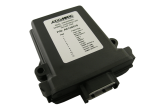
A two-channel signal converter with isolation and CAN bus, this product is designed for diesel engine control systems, industrial automation, vehicle automation and machine control integration. The signal converter accepts two analog current or voltage signals, resistive or digital inputs, PWM or frequency/RPM inputs and converts them into two analog, PWM, frequency or digital signal outputs. A +5V reference powers sensor inputs. The unit has 4-way isolation between power, inputs, outputs and CAN. The I/O control includes CAN bus automation for SAE J1939 12VDC or 24VDC control systems or CANopen networks. It can be installed in control panels, industrial control automation systems, power generator set control systems, off-highway equipment, construction machines and test equipment.| Picture | Product Name | Part Number | Webstore | Downloads | More Information |
|---|---|---|---|---|---|
|
Isolated Signal Converter with CAN |
AX130510 |
- |
16 Analog I/O Module
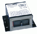
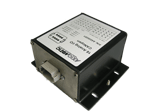
The 16 Universal Signal Input/Analog Output CAN Controller can extend machine control networks by adding I/O to the CAN bus. This controller features one CAN port for user-defined communications over the bus. It accepts up to eight analog (0-5V, 0-10V, 0-20mA or 4-20mA) or digital or PWM frequency inputs and provides eight analog outputs (0-5V, 0-10V, +/-5V, +/-10V, 0-20mA, 4-20mA). Diagnostics messages are provided over the CAN network for the status of inputs or outputs. A RS-232 port is provided for user configuration via PC or for diagnostic purposes.| Picture | Product Name | Part Number | Webstore | Downloads | More Information |
|---|---|---|---|---|---|
|
16 Analog I/O Module |
AX030200 |
- | ||
|
16 Analog I/O Module |
AX030201 |
Please contact sales |
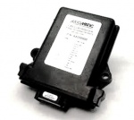
4-Channel Strain Gauge to CAN Controller
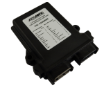
The 4-Channel Strain Gauge CAN controller accepts up to four 4-wire strain gauge connections. The input range is user selectable from +/- 19.5mV to +/- 2.5VDC. It interfaces with the machine’s CAN network (SAE J1939). The measurement rate is 2.5 scans per second and the update rate is 400ms for all four channels. Standard embedded software is provided. Rugged IP67 rated packaging and a power supply input of 12VDC or 24VDC nominal suits applications in the harsh environment of mobile equipment with on-board battery power. All setpoints are user configurable using the Electronic Assistant.
| Picture | Product Name | Part Number | Webstore | Downloads | More Information |
|---|---|---|---|---|---|
|
4-Channel Strain Gauge to CAN Controller |
AX200000 |
Please contact sales |
- |
Connector Amplifier for Proportional Valves – DIN 43650A
(0-10V input, 1.2A output, 2m grey cable, IP65)
The connector amplifier supplies a solenoid valve with current proportional to an input control (0-10VDC or 0-20mA). Application: Accurate control of hydraulic and pneumatic proportional solenoid valves used in mobile construction equipment and industrial processes.
| Picture | Product Name | Part Number | Webstore | Downloads | More Information |
|---|---|---|---|---|---|
|
Connector Amplifier |
AX-CAPV-H-10V-1.2A-6C-2M |
- |
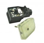
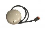
GPS Receiver - CAN J1939
The GPS Receiver – J1939 is a fast update GPS that outputs J1939 data. Its update time is only 0.1 seconds, and it is extremely accurate at capturing position, velocity and time.
| Picture | Product Name | Part Number | Webstore | Downloads | More Information |
|---|---|---|---|---|---|
|
GPS Receiver CAN J1939 - 250 Baud |
GPS-REC-J1939-001 |
- | ||

|
GPS Receiver CAN J1939 - 500 Baud |
GPS-REC-J1939-002 |
System Output Modules
CM0410 Input Output Module
The CM0410 is a general-purpose input/output controller that includes a single J1939 CAN interface, four inputs, one high-side current measurement pass-through and 10 high-side outputs. The main function of the product is to provide a means of controlling relays through J1939 messages on the CAN bus. The CM0410 is a CAN slave module only and supports no standalone operation.
| Picture | Product Name | Part Number | Webstore | Downloads | More Information |
|---|---|---|---|---|---|

|
CM0410 Input Output Module |
CM0410 |
- |
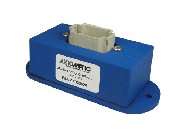
CAN Analog Signal Output Controllers
| Picture | Product Name | Part Number | Webstore | Downloads | More Information |
|---|---|---|---|---|---|
|
CAN Analog Signal Output Controller |
AX030520 |
- | ||

|
CAN Analog Signal Output Controller |
AX030521 |
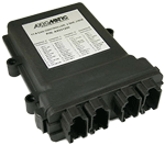
11:9 CAN Controllers
| Picture | Product Name | Part Number | Webstore | Downloads | More Information |
|---|---|---|---|---|---|
|
11:9 Controller |
AX031200 |
- | ||

|
11:9 Controller |
AX031201 |
CAN to 10 Output Valve Controller
Available in 12V, 24V and 48V operating input power modules, this durable CAN-controlled output controller is capable of providing 10 universal outputs at up to 2.5A or 7A for the whole module. Applications include proportional valves, hotshot control profiles, PWM signals and on/off valves. Settings may be user configured via Windows-based Electronic Assistant.
| Picture | Product Name | Part Number | Webstore | Downloads | More Information |
|---|---|---|---|---|---|
|
CAN to 10 Output |
AX021210 |
Please contact sales |
- | ||
|
CAN to 10 Output |
AX021210-01 |
||||
|
CAN to 10 Output |
AX021211 |
CAN (J1939) to 4-Channel Analog Output
The IO device belongs to a family of Axiomatic smart controllers with programmable internal architecture. This provides users with flexibility, allowing them to build their own custom controller with a required functionality from a set of predefined internal functional blocks using the PC-based Axiomatic Electronic Assistant software tool. Application programming is performed through the CAN interface, without disconnecting the controller from the user’s system.
| Picture | Product Name | Part Number | Webstore | Downloads | More Information |
|---|---|---|---|---|---|
|
CAN to 4-Channel |
AX030500 |
- | ||

|
CAN to 4 Channel |
AX030502 |
Please contact sales |
CANopen to 4-Channel Analog Outputs
The 4-Channel Analog Signal Outputs CAN IO device belongs to a family of Axiomatic user-customizable smart controllers. The programmable internal architecture provides users with an ultimate flexibility, allowing them to build their own custom controller with a required functionality from a set of predefined internal functional blocks using any commercially available CANopen tools.
| Picture | Product Name | Part Number | Webstore | Downloads | More Information |
|---|---|---|---|---|---|
| CANopen to 4-Channel Analog Signal Outputs Device |
AX030501 |
- |
TC/Analog Input of CAN Controller
The TC/Analog Inputs to CAN Controller receives inputs from engine coolant, fuel and differential pressure sensors, engine temperature sensors, thermistors as well as thermocouples and is networked to an SAE J1939 based control system. Seven +5V references (10mA) are provided to power the sensors. The two CAN ports are isolated from signal inputs and thermocouple inputs.
| Picture | Product Name | Part Number | Webstore | Downloads | More Information |
|---|---|---|---|---|---|
| TC/Analog Input of CAN Controller |
AX181000 |
- | |||
| Connector Kit |
AX070123 |
Please contact sales |
- |
- |
CAN Enabled Current Driver
The Single 5-amp bi-directional current driver is built from either a MotoHawk ECM S12-24 or ECM 563-48 ECU. This is a customizable solution that allows for custom logic or the use as a simple CAN-based slave. Configuration and service tools are available.
| Picture | Product Name | Part Number | Webstore | Downloads | More Information |
|---|---|---|---|---|---|
|
CAN Enabled |
(Custom) |
Built upon the
|
- |
- |
Multiplexed Power Distribution Module (MPDM)
The New Eagle Multiplexed Power Distribution Module offers economical CAN Network oversight for high power circuits in vehicle power distribution. Manufactured as a hardened and weather tight module, it may be configured to provide various OEM circuit protection and switching functions using industry standard fuses, relays and breakers, with the status and control of each circuit accessible through J1939/CANopen messages.
| Picture | Product Name | Part Number | Webstore | Downloads | More Information |
|---|---|---|---|---|---|
|
Multiplexed Power |
MPDM-NE1 |
||||
|
MPDM-31M-300-0 |
DC-DC Converter
The DC/DC converter is suitable for application on charging/cranking battery-based systems. Power from a vehicle battery is conditioned at the same voltage level and isolation is provided to protect onboard electronic devices.
| Picture | Product Name | Part Number | Webstore | Downloads | More Information |
|---|---|---|---|---|---|
|
Axiomatic Isolated 24VDC/24VDC Converter |
AX081530 |
- | |||
| AX081530K (with 2mm cable) |
High Current H-Bridge Module
The H-Bridge module is a solid state, DC load reversing switch that is wired in an H-Bridge configuration. Rated for up to 30A at 24VDC, this device provides an efficient way to reverse polarity on a variety of DC loads, including solenoids, motors and brake/clutch assemblies. A J1939 CAN-controlled variant of the H-Bridge module is available for purchase. The CAN communications allow for greater control of the device, including current feedback and limiting. The module uses wired signals to adjust the J1939 source address for multiple identical devices on a given bus. A predefined DBC file for the CAN-controlled variant is also available for purchase.
| Picture | Product Name | Part Number | Webstore | Downloads | More Information |
|---|---|---|---|---|---|
|
Rugged 30A H-Bridge |
HB-30A |
- | |||
|
Rugged 30A H-Bridge |
HB-30A-J1939 |
||||
|
Rugged 30A H-Bridge |
HB-30A-J1939-DBC |
||||
|
Connector Kit for |
CONKIT-HB-30A |
CAN Enabled Current Driver
The Single 5-amp bi-directional current driver is built from either a MotoHawk ECM S12-24 or ECM 563-48 ECU. This is a customizable solution that allows for custom logic or the use as a simple CAN-based slave. Configuration and service tools are available.
| Picture | Product Name | Part Number | Webstore | Downloads | More Information |
|---|---|---|---|---|---|
|
Remote Mount Solenoid Driver – DIN Rail Mount |
AX-RSD-DR-4-20MA-2A |
- |
Protocol Converters
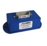
2 SAE J1939, SAE J1587
| Picture | Product Name | Part Number | Webstore | Downloads | More Information |
|---|---|---|---|---|---|
|
Protocol Converter, |
AX140400 |
- |
LIN to CAN Protocol Converter
The LIN-CAN Protocol Converter, SAE J1939 exchanges data between a LIN network and a CAN network. This device is J1939 compliant and can be configured with the Axiomatic Electronic Assistant PC tool.Digital Keypads
4-Position Keypad
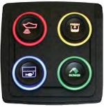
Hassle-free control and customization is literally at your fingertips. The Power Key is reconfigurable, readdressable and relegendable, requiring only a laptop or PC connection. Its secure-locking inserts (not included in purchase) can be interchanged to match the configuration.
| Picture | Product Name | Part Number | Webstore | Downloads | More Information |
|---|---|---|---|---|---|
|
Powerkey Pro 4 Position CAN, Deutch Conn. |
KEYPAD-DS-004-02 |
Please contact sales |
- |
- |
8-Position Keypad
This standard keypad allows a designer to build a semi-custom system for a minimal cost. Each keypad is made from extremely high-quality and rugged silicone that can be laser etched with specified button legends, text or company logos. Communication protocols include RS485, J1030/J1939-11, CANopen and others.
| Picture | Product Name | Part Number | Webstore | Downloads | More Information |
|---|---|---|---|---|---|
|
8-Position CAN Keypad |
KEYPAD-DS-008-02 |
- |
Note: CAN DBC file available upon request.
Specialty IO Modules
J1772 Vehicle Power Interface Module (VPIM)
The J1772 Vehicle Power Interface Module (VPIM) provides the necessary circuitry to interface with Electric or plug-in Hybrid Electric vehicle charging equipment in accordance with the SAE J1772 specifications. It allows the vehicle systems and ECUs that require a low current "sleep" mode to be managed externally and monitors the inputs, providing an output that will drive an external "Wake Up" relay which, in turn, provides power to the connected systems.
| Picture | Part Number | Webstore | Downloads | More Information |
|---|---|---|---|---|
|
VPIM-024-1301 |
PWM to Analog Converter (Pedal Emulator)
The New Eagle PWM to Analog Converter converts three separate channels of PWM signals to proportional 0-5V analog signals. The converter is especially useful when paired with control modules with PWM outputs, but no 0-5V analog outputs. This device is very useful as a pedal emulator.
| Picture | Part Number | Webstore | Downloads | More Information |
|---|---|---|---|---|
|
PWM-AN-024-1403 |
DBW PWM to Analog Pedal Emulator
The New Eagle DBW PWM to Analog Converter is optimized to operate in Drive-By-Wire (DBW) applications. It is designed to take the Raw Analog and Digital signals from the accelerator and brake pedals respectively and either pass the signal through to the OEM ECU or override the signals with commanded PWM signals from the DBW Aftermarket ECU.
| Picture | Part Number | Webstore | Downloads | More Information |
|---|---|---|---|---|
|
PWM-DBW-024-2001 |
Please contact sales |
|||
|
PWM-DBW-024-2002 |
LVDT Simulator for LVDT or RVDT Sensors
The LVDT Simulator is used to test LVDT or RVDT sensors. Using a 0-10VDC command signal input and an excitation (drive input), the unit provides two simulation outputs of 1-5VAC. An internal 3kHz oscillator can be utilized as an alternative excitation source. Both outputs are fully isolated. The unit accepts power supply input from 4-32VDC. When the input voltage increases from 0 to 10VDC, the output voltage A increases from 1 to 5VAC and the output voltage B decreases from 5 to 1VAC. Factory settings for the offset (minimum) and span (maximum) are user adjustable. A LED indicates power is ON. The unit is conformal coated and available in a DIN rail mount housing.
| Picture | Part Number | Webstore | Downloads | More Information |
|---|---|---|---|---|
|
AX-LVDTS-DR-03 |
- |
Electronic Assistant
The Electronic Assistant® is a software configuration tool that runs on the Windows operating system and is connected to a J1939 bus via a USB to CAN converter, AX070501. Upon being connected to the bus, the EA will find all IO devices on the bus and recognize those manufactured by Axiomatic. Using this tool, a user can quickly configure an Axiomatic IO device for the desired performance over a wide variety of applications.
| Picture | Part Number | Webstore | Downloads | More Information |
|---|---|---|---|---|
|
AX070502 |
- |
Electronic Assistant and CANopen
Axiomatic offers CANopen-ready modules that do not require the Axiomatic Electronic Assistant software configuration tool.
The parameters in Axiomatic CANopen products can be read or written through any standard CANopen tool that can access an ECU's Object Dictionary. In addition to the User Manual, Axiomatic also provides Electronic Data Sheets (EDS) with all their CANopen ECUs, as per the standard "CiA DSP 306 V1.3, Electronic Data Sheet Specification for CANopen (EDS)".
Axiomatic User Manuals
To view detailed user manuals for Axiomatic products, click here. Password: trillium
Discontinued Products
| Picture | Product Name | Part Number | Replacement |
|---|---|---|---|
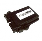
|
10 ANALOG INPUT MODULE, SAE J1939 | AX030100 | AX030120 |

|
10 ANALOG INPUT MODULE, CANOPEN | AX030101 | AX030121 |
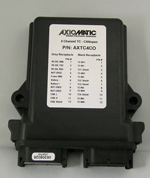
|
Thermocouple Module |
AXTC4CO |
Please contact sales |
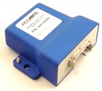
|
Dual Universal Signal Converter |
AX130500 |
Please contact sales |
