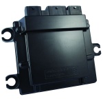
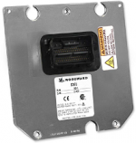
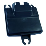
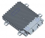
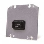
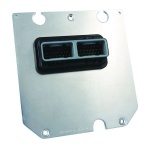
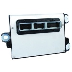
Controllers: Difference between revisions
| Line 1: | Line 1: | ||
[[file:Background5.png|left|700px|MotoHawk Controllers Lineup]] | |||
<br clear="all"/> | |||
{{TOClimit|4}} | |||
=<div style="font-size:21px; width:75%; font-weight:bold; text-align:left; padding-top:7px; padding-bottom:7px; background:#800020; color:white;">Introduction to New Eagle Controllers</div>= | |||
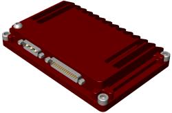
New Eagle sells Raptor-enabled controller hardware and a select set of MotoHawk controllers. | |||
In general, we have the following categories for controllers: | |||
* | *Body Control Modules (BCMs) | ||
*Engine Control Modules (ECMs) | |||
*Raptor Control Modules (RCMs) | |||
*General Control Modules (GCMs) | |||
*Hydraulic Control Modules (HCMs) | |||
*Telematics Control Modules (TCMs) | |||
The controllers range in pin count, input, output, memory and processor configuration. Although a controller may have a function listed, such as Body Control Module (BCM), it is able to be used in other functions. Typically, the controller for a particular application is selected based on hardware capability such as I/O need, processor capability, communication requirements and voltage operating range. The exception to this rule is engine control, where specialized hardware is required for decoding the CRANK/CAM inputs for engine timing - here an engine control module is required. | |||
Most modules are available in ‘F’ (Flash) or ‘C’ (Calibratable) versions. Flash modules are typically used for production purposes. Calibratable modules are typically for prototyping/development purposes and can be calibrated in real time using [[Raptor-Cal]] or another calibration tool. | |||
Contact our '''[mailto:sales@neweagle.net sales team]''' for assistance with questions regarding the selection of your electronic controller. | |||
=<div style="font-size:21px; width:75%; font-weight:bold; text-align:left; padding-top:7px; padding-bottom:7px; background:#800020; color:white;">Raptor Controllers</div>= | |||
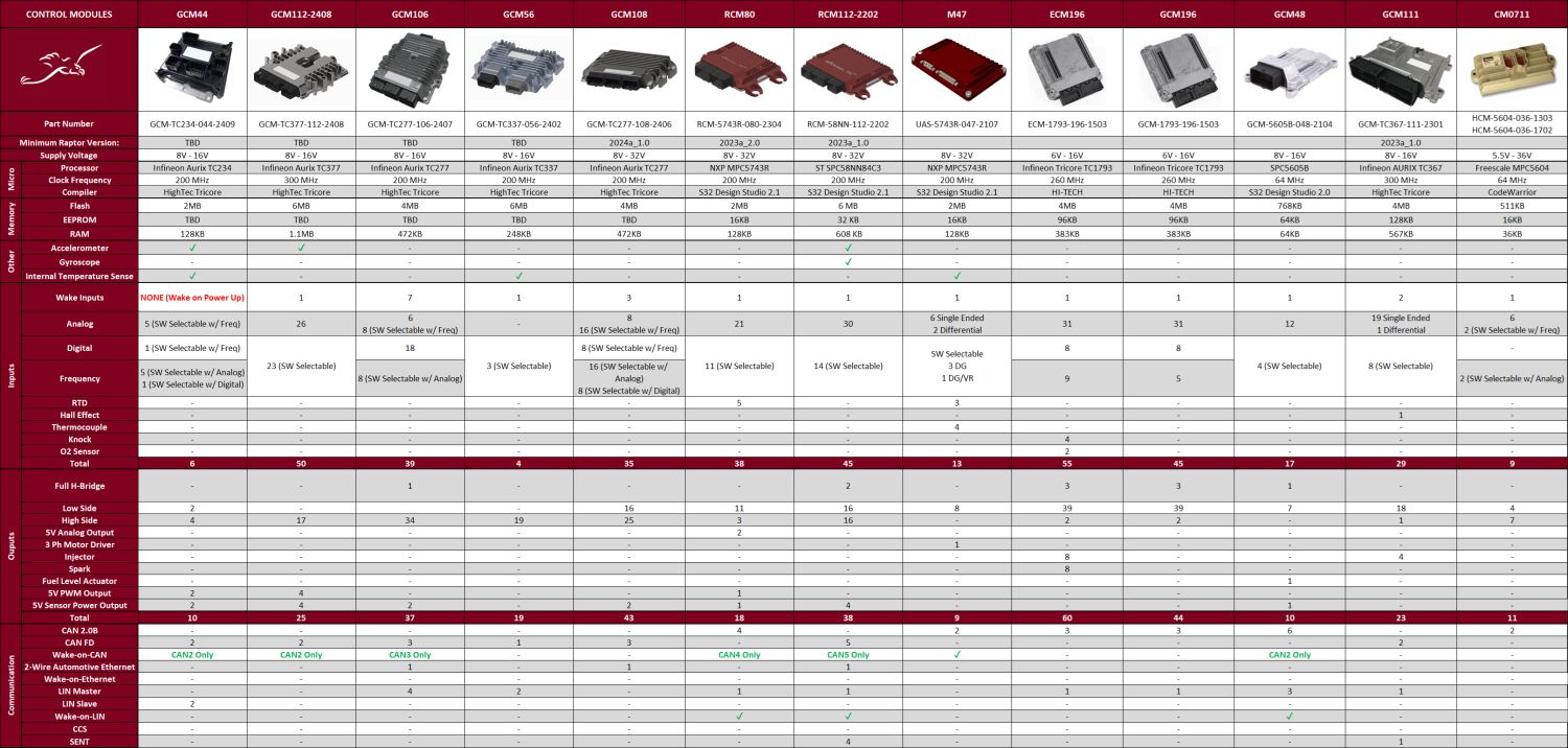
[[File:RaptorController_Comparison.png|1500px]] | |||
==<div style="font-size:21px; width:75%; font-weight:bold; text-align:left; padding-top:7px; padding-bottom:7px; background:#800020; color:white;">Compilers</div>== | |||
The compilers for the following Raptor Controllers can be found '''[https://wiki.neweagle.net//index.php?title=Raptor_Controller_Compilers here]'''. | |||
==<div style="font-size:21px; width:75%; font-weight:bold; text-align:left; padding-top:7px; padding-bottom:7px; background:#800020; color:white;">Raptor Control Modules (RCM)</div>== | |||
===RCM-5743R-080-2304 (RCM80) === | |||
{{RCM-5743R-080}} | |||
===RCM-58NN-112-2202 (RCM112)=== | |||
{{RCM-58NN-112}} | |||
==<div style="font-size:21px; width:75%; font-weight:bold; text-align:left; padding-top:7px; padding-bottom:7px; background:#800020; color:white;">John Deere M Series Raptor Control Module (GCM)</div>== | |||
===GCM-TC337-056-2402 (M502)=== | |||
{{GCM-TC337-056}} | |||
===GCM-TC277-108-2406 (M501)=== | |||
{{GCM-TC277-108}} | |||
===GCM-TC277-106-2407 (M702)=== | |||
{{GCM-TC277-106}} | |||
===GCM-TC377-112-2408 (M411)=== | |||
{{GCM-TC377-112}} | |||
===GCM-TC234-044-2409 (M31)=== | |||
{{GCM-TC234-044}} | |||
==<div style="font-size:21px; width:75%; font-weight:bold; text-align:left; padding-top:7px; padding-bottom:7px; background:#800020; color:white;">General Control Modules (GCM)</div>== | |||
===GCM-5605B-048-2104 (GCM48)=== | |||
{{GCM-5605B-048}} | |||
===GCM-TC367-111-2301 (GCM111)=== | |||
{{GCM-TC367-111-2301}} | |||
===GCM-1793-196-1503 (GCM196)=== | |||
{{GCM-1793-196-1503}} | |||
==<div style="font-size:21px; width:75%; font-weight:bold; text-align:left; padding-top:7px; padding-bottom:7px; background:#800020; color:white;">Engine Controller Modules (ECM)</div>== | |||
===ECM-1793-196-1503 (ECM196)=== | |||
{{ECM-1793-196-1503}} | |||
==<div style="font-size:21px; width:75%; font-weight:bold; text-align:left; padding-top:7px; padding-bottom:7px; background:#800020; color:white;">Hydraulic Control Modules (HCM)</div>== | |||
===HCM-5604-036 (CM0711)=== | |||
{{HCM-5604-036-1303}} | |||
==<div style="font-size:21px; width:75%; font-weight:bold; text-align:left; padding-top:7px; padding-bottom:7px; background:#800020; color:white;">UAV/UAS Modules</div>== | |||
===UAS-5743R-047-2107 (UAS47)=== | |||
{{UAS-5743R-047}} | |||
==<div style="font-size:21px; width:75%; font-weight:bold; text-align:left; padding-top:7px; padding-bottom:7px; background:#800020; color:white;">Obsolete Modules</div>== | |||
===GCM70 Family=== | |||
{{GCM-5634M-070}} | |||
===GCM-5634M-070-1759 (GCM70-1759)=== | |||
{{GCM-5634M-070-1759}} | |||
===BCM-5646-48-1404 (BCM48) === | |||
{{BCM-5646-48-1404}} | |||
===GCM-5605B-048-2008=== | |||
{| class="wikitable" style="text-align: center;" cellpadding = "5" | |||
!scope="col"|Picture | |||
!scope="col"|Part Number | |||
!scope="col"|Webstore | |||
!scope="col"|Downloads | |||
!scope="col"|More Information | |||
|- | |||
|style = "height:180px; width:180px;"| | |||
[[File:GCM48.png|150px]] | |||
|style = "height:180px; width:180px;"| | |||
''' | GCM-5605B-048-2008 | ||
|style = "height:180px; width:180px;"| | |||
'''-''' | |||
|style = "height:180px; width:180px;"| | |||
'''[[GCM48#Datasheets|Datasheet]]''' | |||
|style = "height:180px; width:300px;"| | |||
'''[[GCM48| More Details]]''' | |||
|} | |||
===GCM80 Family=== | |||
{| class="wikitable" style="text-align: center;" cellpadding = "5" | |||
!scope="col"|Processor | |||
!scope="col"|Inputs | |||
!scope="col"|Outputs | |||
!scope="col"|Communications | |||
!scope="col"|Operating Voltage | |||
|- | |||
|style = "height:20px; width:180px;"| | |||
MPC5607B, 64 MHz | |||
|style = "height:20px; width:180px;"| | |||
32 | |||
|style = "height:20px; width:180px;"| | |||
16 | |||
|style = "height:20px; width:180px;"| | |||
4 CAN 2.0B | |||
|style = "height:20px; width:300px;"| | |||
9-16VDC | |||
|} | |||
{| class="wikitable" style="text-align: center;" cellpadding = "5" | |||
!scope="col"|Picture | |||
!scope="col"|Part Number | |||
!scope="col"|Webstore | |||
!scope="col"|Downloads | |||
!scope="col"|More Information | |||
|- | |||
|style = "height:180px; width:180px;"| | |||
[[File:GCM80.png|150px]] | |||
|style = "height:180px; width:180px;"| | |||
GCM-5607B-080-1901<br> | |||
GCM-5607B-080-1903<br> | |||
<span style="font-size:78%> | |||
|style = "height:180px; width:180px;"| | |||
- | '''-''' | ||
|style = "height:180px; width:180px;"| | |||
'''[[GCM80#Datasheets|Datasheet]]'''<br> | |||
'''[[GCM80#CAD|CAD]]''' | |||
|style = "height:180px; width:300px;"| | |||
'''[[GCM80 | More Details]]''' | |||
|} | |||
- | ===HCM-ARM4-70-1401 (CM3620)=== | ||
{{HCM-ARM4-70-1401}} | |||
===HCM-5534-90-1302 (CM3626)=== | |||
{{HCM-5534-90-1302}} | |||
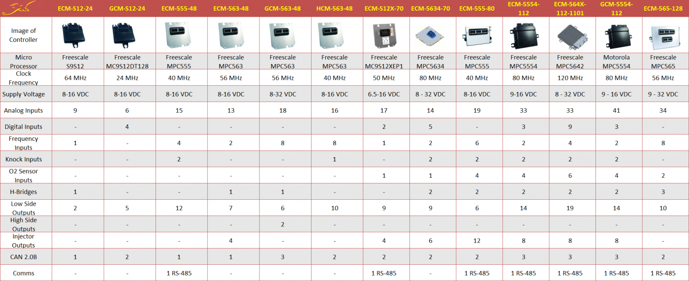
=<div style="font-size:21px; width:75%; font-weight:bold; text-align:left; padding-top:7px; padding-bottom:7px; background:#800020; color:white;">MotoHawk Modules</div>= | |||
<div style="overflow:scroll"> | |||
[[File:MotoHawkControllerComparisonChart.png|1400px]] | |||
</div> | |||
=== | ==<div style="font-size:21px; width:75%; font-weight:bold; text-align:left; padding-top:7px; padding-bottom:7px; background:#800020; color:white;">Engine Control Modules (ECM)</div>== | ||
===ECM-563-48 (ECM48)=== | |||
{{ECM-563-48}} | |||
=== | === ECM-5554-112 (ECM112)=== | ||
{{ECM-5554-112}} | |||
= | === ECM-S12X-70 (ECM70)=== | ||
{{ECM-S12X-070}} | |||
=== ECM-S12-24 (SECM24) === | |||
{{ECM-S12-24}} | |||
ECM | === SECM112 === | ||
{{ECM-564X-112}} | |||
=== PCM112-14 === | |||
{{ECM-5644-112}} | |||
===SECM70=== | |||
{{ECM-5634-70}} | |||
==<div style="font-size:21px; width:75%; font-weight:bold; text-align:left; padding-top:7px; padding-bottom:7px; background:#800020; color:white;">General Control Modules (GCM)</div>== | |||
: | |||
: | |||
: | |||
: | |||
: | |||
: | |||
: | |||
=== GCM-563-48 (GCM48) === | |||
{{GCM-563-48}} | |||
=== GCM-S12-24 (MCHI)=== | |||
{{GCM-S12-24}} | |||
==<div style="font-size:21px; width:75%; font-weight:bold; text-align:left; padding-top:7px; padding-bottom:7px; background:#800020; color:white;">Hydraulic Control Modules (HCM)</div>== | |||
: | |||
: | |||
: | |||
: | |||
: | |||
=== HCM-563-48 (HCM48) === | |||
==HCM== | {{HCM-0563-048}} | ||
==<div style="font-size:21px; width:75%; font-weight:bold; text-align:left; padding-top:7px; padding-bottom:7px; background:#800020; color:white;">Obsolete Modules</div>== | |||
: | ===GCM 565-24 (ISDL) === | ||
:: | {{GCM-565-24}} | ||
:: | |||
:: | |||
===ECM-555-80 (PCM80)=== | |||
{{ECM-555-80}} | |||
=== ECM-565-128 (PCM128)=== | |||
{{ECM-0565-128}} | |||
===ECM-555-48 (ECM48)=== | |||
{{ECM-554-48}} | |||
== | === GCM-5554-112 (GCM112)=== | ||
{{GCM-5554-112}} | |||
=== GCM-S12-62 (DCSM)=== | |||
{{GCM-S12-62}} | |||
== | =Naming, General Controller FAQs, Webstore, Warranty info= | ||
==New Eagle Control Module Naming Scheme== | |||
The New Eagle naming scheme is broken into four main parts: type of control module, type of microprocessor, number of pins, and model year and variant. An extra sequence of numbers/letters may be seen at the end which determine certain model features such as flash, calibratable or mounting feet. | |||
'''ECM-565-128-0701-C-M''' | |||
*Start by looking at the first section which determines the type of control model. The model in the above example is an ECM (Engine Control Module) as opposed to a GCM (General Control Module), HCM (Hydraulic Control Module), or BCM (Body Control Module) | |||
*The second part describes the type of microprocessor the module has. The above module has a MPC565 microprocessor. | |||
*The third part shows the number of pins that the module has. The example module has 128 pins. | |||
*The fourth section consists of the model year and the model variant. In the above example, the control module has a model year of 2007 and is the first variant. | |||
*The next section that may appear when naming modules determines certain features that the model may have. 'C' stands for Calibratable; thus, the above module is calibratable. Other endings may include 'F' (Flash), 'M' (Mounting Feet), 'CPO' (Calibratable "DEV" Development Module) and 'F00' (Flash "PROD" Production Module). | |||
*The last spot will either have an 'M' or be blank. 'M' means mounting feet are included. | |||
'''Module Naming Cheat Sheet:''' | |||
Module: ECM-555-80-xxyy-Czz-M or F-M | |||
= | ECM = engine control module | ||
= | 555 = MPC555 microprocessor | ||
80 = 80 pins | |||
= | xx = model year (e.g. 07 = 2007 model year) | ||
= | yy = variant of 80-pin model for xx model year (e.g. 03 = third variant). | ||
Czz = calibratable "DEV" development module (zz is the development level (i.e. P1 - prototype level 1)) | |||
F = flash "PROD" production module | |||
The final letter is 'M,' meaning rubber mounting feet are attached. If the part number does not end in an 'M,' the module will not come with feet. | |||
For | ==General Controller FAQ== | ||
'''[[MotoHawk_Hardware#Specific_Controller_Information|Controller FAQs]]'''<br>This section describes information common across modules. For specific module information, go to the controller page for that module family. | |||
==Webstore== | |||
'''[https://store.neweagle.net/product-category/products-by-category/controllers/ Controllers]''' | |||
==Usage Warranty Policy== | |||
A production supply agreement (PSA) is recommended to apply for potential future warranty returns. A PSA would include information on the use of the I/O and intended/designed/specified mode of operation of this I/O. | |||
New Eagle does not know how a customer may apply the module and thus does not provide warranty without an express and specific production supply agreement based on the cumulative operating mode (which requires manufacturer testing/approval to validate). | |||
and the | |||
Most products sold as engineering prototypes do not have warranty. The details are covered in the terms and conditions of sale. | |||
New Eagle Engineering is available to assist to validate your application to the module design, hence providing the ability to gain a warranty for your recurring production use. | |||
Latest revision as of 12:07, 16 August 2024

Introduction to New Eagle Controllers
New Eagle sells Raptor-enabled controller hardware and a select set of MotoHawk controllers.
In general, we have the following categories for controllers:
- Body Control Modules (BCMs)
- Engine Control Modules (ECMs)
- Raptor Control Modules (RCMs)
- General Control Modules (GCMs)
- Hydraulic Control Modules (HCMs)
- Telematics Control Modules (TCMs)
The controllers range in pin count, input, output, memory and processor configuration. Although a controller may have a function listed, such as Body Control Module (BCM), it is able to be used in other functions. Typically, the controller for a particular application is selected based on hardware capability such as I/O need, processor capability, communication requirements and voltage operating range. The exception to this rule is engine control, where specialized hardware is required for decoding the CRANK/CAM inputs for engine timing - here an engine control module is required.
Most modules are available in ‘F’ (Flash) or ‘C’ (Calibratable) versions. Flash modules are typically used for production purposes. Calibratable modules are typically for prototyping/development purposes and can be calibrated in real time using Raptor-Cal or another calibration tool.
Contact our sales team for assistance with questions regarding the selection of your electronic controller.
Raptor Controllers
Compilers
The compilers for the following Raptor Controllers can be found here.
Raptor Control Modules (RCM)
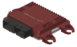
RCM-5743R-080-2304 (RCM80)
| Controller | Processor | Inputs | Outputs | Communications | Operating Voltage |
|---|---|---|---|---|---|
|
RCM80-2304 |
MPC5743R, 200 MHz |
38 |
17 |
4 CAN 2.0B |
8-32VDC |
| Picture | Part Number | Webstore | Downloads | More Information |
|---|---|---|---|---|
|
RCM-5743R-080-2304 |
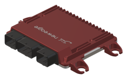
RCM-58NN-112-2202 (RCM112)
| Controller | Processor | Inputs | Outputs | Communications | Operating Voltage |
|---|---|---|---|---|---|
|
RCM112-2202 |
SPC58NN, 200 MHz |
43 |
40 |
5 CAN FD |
8-32VDC |
| Picture | Part Number | Webstore | Downloads | More Information |
|---|---|---|---|---|
|
RCM-58NN-112-2202 |
John Deere M Series Raptor Control Module (GCM)
GCM-TC337-056-2402 (M502)
| Processor | Inputs | Outputs | Communications | Operating Voltage |
|---|---|---|---|---|
|
Infineon Aurix TC337 |
4 |
19 |
1 CAN FD |
8V-16V |
| Picture | Part Number | Webstore | Downloads | More Information |
|---|---|---|---|---|
|
GCM-TC337-056-2402 |
GCM-TC277-108-2406 (M501)
| Processor | Inputs | Outputs | Communications | Operating Voltage |
|---|---|---|---|---|
|
Infineon Aurix TC277 |
35 |
43 |
3 CAN FD |
8V-16V |
| Picture | Part Number | Webstore | Downloads | More Information |
|---|---|---|---|---|
|
GCM-TC277-108-2406 |
GCM-TC277-106-2407 (M702)
| Processor | Inputs | Outputs | Communications | Operating Voltage |
|---|---|---|---|---|
|
Infineon Aurix TC277 |
39 |
37 |
3 CAN FD |
8V-16V |
| Picture | Part Number | Webstore | Downloads | More Information |
|---|---|---|---|---|
|
GCM-TC277-106-2407 |
GCM-TC377-112-2408 (M411)
| Processor | Inputs | Outputs | Communications | Operating Voltage |
|---|---|---|---|---|
|
Infineon Aurix TC377 |
50 |
25 |
2 CAN FD |
8V-16V |
| Picture | Part Number | Webstore | Downloads | More Information |
|---|---|---|---|---|
|
GCM-TC377-112-2408 |
GCM-TC234-044-2409 (M31)
| Processor | Inputs | Outputs | Communications | Operating Voltage |
|---|---|---|---|---|
|
Infineon Aurix TC234 |
6 |
10 |
2 CAN FD |
8V-16V |
| Picture | Part Number | Webstore | Downloads | More Information |
|---|---|---|---|---|
|
GCM-TC234-044-2409 |
General Control Modules (GCM)
GCM-5605B-048-2104 (GCM48)
| Processor | Inputs | Outputs | Communications | Operating Voltage |
|---|---|---|---|---|
|
SPC5605B, 64 MHz |
16 |
9 |
6 CAN 2.0B |
8-16VDC |
| Picture | Part Number | Webstore | Downloads | More Information |
|---|---|---|---|---|
|
GCM-5605B-048-2104 |
GCM-TC367-111-2301 (GCM111)
| Processor | Inputs | Outputs | Communications | Operating Voltage |
|---|---|---|---|---|
|
300 MHz |
31 |
23 |
2 CAN, 1 LIN |
8-16VDC |
| Picture | Part Number | Webstore | Downloads | More Information |
|---|---|---|---|---|
|
GCM-TC367-111-2301 |
GCM-1793-196-1503 (GCM196)
| Processor | Inputs | Outputs | Communications | Operating Voltage |
|---|---|---|---|---|
|
260 MHz Infineon Tricore TC1793 |
45 |
45 |
3 CAN, 1 LIN |
6-16VDC |
| Picture | Part Number | Webstore | Downloads | More Information |
|---|---|---|---|---|
|
GCM-1793-196-1503 |
Engine Controller Modules (ECM)
ECM-1793-196-1503 (ECM196)
| Processor | Inputs | Outputs | Communications | Operating Voltage |
|---|---|---|---|---|
|
260MHz Infineon Tricore TC1793 |
50 |
84 |
3 CAN, 1 LIN |
6-16VDC |
| Picture | Part Number | Webstore | Downloads | More Information |
|---|---|---|---|---|
|
ECM-1793-196-1503 |
Please contact sales |
Hydraulic Control Modules (HCM)
HCM-5604-036 (CM0711)
| Processor | Inputs | Outputs | Communications | Operating Voltage |
|---|---|---|---|---|
|
64 MHz Freescale 32 bit |
7 |
11 |
2 CAN |
5.5-36VDC |
| Picture | Part Number | Webstore | Downloads | More Information |
|---|---|---|---|---|
|
HCM-5604-036-1303 |
UAV/UAS Modules
UAS-5743R-047-2107 (UAS47)
| Controller | Processor | Inputs | Outputs | Communications | Operating Voltage |
|---|---|---|---|---|---|
|
UAS47-2107 |
MPC5743R, 200 MHz |
19 |
11 |
2 CAN 2.0B |
8-32VDC |
| Picture | Part Number | Webstore | Downloads | More Information |
|---|---|---|---|---|
|
UAS-5743R-047-2107 |
Obsolete Modules
GCM70 Family
| Controller | Processor | Inputs | Outputs | Communications | Operating Voltage |
|---|---|---|---|---|---|
|
GCM-5634M-070-1559 |
MPC5634M, 80 MHz |
22 |
19 |
2 CAN 2.0B |
8-32VDC |
|
GCM-5634M-070-1562 |
28 |
26 | |||
|
GCM-5642A-070-1702 |
MPC5642A, 120 MHz |
28 |
26 |
| Picture | Part Number | Webstore | Downloads | More Information |
|---|---|---|---|---|
|
GCM-5634M-070-1559 |
Please contact sales |
GCM-5634M-070-1759 (GCM70-1759)
| Processor | Inputs | Outputs | Communications | Operating Voltage |
|---|---|---|---|---|
|
MPC5634M, 80 MHz |
22 |
19 |
2 CAN 2.0B |
8-32VDC |
| Picture | Part Number | Webstore | Downloads | More Information |
|---|---|---|---|---|
|
GCM-5634M-070-1759 |
Please contact sales |
BCM-5646-48-1404 (BCM48)
| Processor | Inputs | Outputs | Communications | Operating Voltage |
|---|---|---|---|---|
|
120 MHz Freescale |
20 |
15 |
4 CAN, 4 LIN, 1 Ethernet |
9-16VDC |
| Picture | Part Number | Webstore | Downloads | More Information |
|---|---|---|---|---|
|
BCM-5646-48-1404 |
Please contact sales |
GCM-5605B-048-2008
| Picture | Part Number | Webstore | Downloads | More Information |
|---|---|---|---|---|
|
GCM-5605B-048-2008 |
- |
GCM80 Family
| Processor | Inputs | Outputs | Communications | Operating Voltage |
|---|---|---|---|---|
|
MPC5607B, 64 MHz |
32 |
16 |
4 CAN 2.0B |
9-16VDC |
| Picture | Part Number | Webstore | Downloads | More Information |
|---|---|---|---|---|
|
GCM-5607B-080-1901 |
- |
HCM-ARM4-70-1401 (CM3620)
| Processor | Inputs | Outputs | Communications | Operating Voltage |
|---|---|---|---|---|
|
48 MHz Arm 32 bit |
36 |
20 |
2 CAN |
7.5-32VDC |
| Picture | Part Number | Webstore | Downloads | More Information |
|---|---|---|---|---|
|
HCM-ARM4-070-1401 |
Please contact sales |
HCM-5534-90-1302 (CM3626)
| Processor | Inputs | Outputs | Communications | Operating Voltage |
|---|---|---|---|---|
|
80 MHz Dual Freescale MPC5534 |
36 |
26 |
2 CAN |
6-32VDC |
| Picture | Part Number | Webstore | Downloads | More Information |
|---|---|---|---|---|
|
HCM-5534-090-1201 HCM-5534-090-1302 HCM-5534-090-1601 HCM-5534-090-1602 |
Please contact sales |
MotoHawk Modules
Engine Control Modules (ECM)
ECM-563-48 (ECM48)
| Processor | Inputs | Outputs | Communications | Operating Voltage |
|---|---|---|---|---|
|
56 MHz Freescale MPC 563 |
15 |
21 |
1 CAN |
8-16VDC |
| Picture | Part Number | Webstore | Downloads | More Information |
|---|---|---|---|---|
|
ECM-563-48-0701-F |
Please contact sales |
| ||
|
ECM-563-48-0701-C |
Please contact sales | |||
|
ECM-563-48-0704-F |
Please contact sales | |||
|
ECM-563-48-0704-C |
Please contact sales | |||
|
ECM-563-48-0705-F |
Please contact sales | |||
|
ECM-563-48-0705-C |
Please contact sales |
ECM-5554-112 (ECM112)
| Processor | Inputs | Outputs | Communications | Operating Voltage |
|---|---|---|---|---|
|
80 MHz Freescale MPC 5554 |
43 |
35 |
3 CAN, 1 RS485 |
9-16VDC |
| Picture | Part Number | Webstore | Downloads | More Information |
|---|---|---|---|---|
|
ECM-5554-112-0902 |
(Discontinued) |
| ||
|
ECM-5554-112-0904 |
ECM-S12X-70 (ECM70)
| Processor | Inputs | Outputs | Communications | Operating Voltage |
|---|---|---|---|---|
|
50 MHz Freescale MC9S12XEP100 |
26 |
20 |
2 CAN, 1 RS485 |
6.5-16VDC |
| Picture | Part Number | Webstore | Downloads | More Information |
|---|---|---|---|---|
|
ECM-S12X-070-1001-C |
More Details |
ECM-S12-24 (SECM24)
| Processor | Inputs | Outputs | Communications | Operating Voltage |
|---|---|---|---|---|
|
64Mhz Freescale S9S12 |
10 |
7 |
1 CAN |
8-16VDC |
| Picture | Part Number | Webstore | Downloads | More Information |
|---|---|---|---|---|
|
ECM-0S12-024-0801-C |
Please contact sales |
| ||
|
ECM-0S12-024-0801-F |
Please contact sales | |||
|
ECM-0S12-024-0802-C |
Please contact sales |
|||
|
ECM-0S12-024-0802-F |
||||
|
ECM-0S12-024-0804-C |
Please contact sales |
|||
|
ECM-0S12-024-0804-F |
SECM112
| Processor | Inputs | Outputs | Communications | Operating Voltage |
|---|---|---|---|---|
|
120 MHz MPC5642 (flash) and MPC5644 (cal) |
50 |
39 |
3 CAN |
8-32VDC |
| Picture | Part Number | Webstore | Downloads | More Information |
|---|---|---|---|---|
|
ECM-5642-112-1304-F |
Product Manual available upon request with NDA. Please contact sales | |||
|
ECM-5644-112-1204-C |
PCM112-14
| Processor | Inputs | Outputs | Communications | Operating Voltage |
|---|---|---|---|---|
|
120 MHz MPC5644A (Main) and 24 MHz S12G128 (Aux) |
49 |
38 |
3 CAN |
8-16VDC |
| Picture | Part Number | Webstore | Downloads | More Information |
|---|---|---|---|---|
|
ECM-5644-112-064-1400-C |
Please contact sales |
More information available upon request with NDA. Please contact sales |
SECM70
| Processor | Inputs | Outputs | Communications | Operating Voltage |
|---|---|---|---|---|
|
80 MHz Freescale MPC5634 |
22 |
26 |
2 CAN |
8-32VDC |
| Picture | Description | Webstore | Downloads | More Information |
|---|---|---|---|---|
|
PN: SECM70-1562-MI-F |
||||
|
PN: SECM70-1512-MI-C SECM70 Mobil Industrial Calibratable WW: ECM-5634M-070-061-1512 |
Please contact sales | |||
|
PN: SECM70-1563-PG-F |
None Available, See Hardware Manual | |||
|
PN: SECM70-1513-PG-C |
Please contact sales | |||
|
PN: SECM70-1559-SK-F |
||||
|
PN: SECM70-1509-SK-C |
Please contact sales | |||
|
PN: SECM70-1565-OH-F |
Please contact sales | |||
|
PN: SECM70-1515-OH-C |
Please contact sales | |||
|
PN: SECM70-1566-LV-F |
Please contact sales | |||
|
PN: SECM70-1516-LV-C |
Please contact sales | |||
|
PN: SECM70-1403-PG-F |
Please contact sales | |||
|
PN: SECM70-1452-MI-F |
General Control Modules (GCM)
GCM-563-48 (GCM48)
| Processor | Inputs | Outputs | Communications | Operating Voltage |
|---|---|---|---|---|
|
56 MHz Freescale MPC563 |
20 |
11 |
3 CAN |
8-32VDC |
| Picture | Part Number | Webstore | Downloads | More Information |
|---|---|---|---|---|
|
GCM-0563-048-0801-C |
| |||
|
GCM-0563-048-0801-F |
||||
|
GCM-0563-048-0802-C |
||||
|
GCM-0563-048-0802-F |
GCM-S12-24 (MCHI)
| Processor | Inputs | Outputs | Communications | Operating Voltage |
|---|---|---|---|---|
|
24 MHz Freescale MC9S12DT128 |
10 |
5 |
2 CAN |
8-16VDC |
| Picture | Part Number | Webstore | Downloads | More Information |
|---|---|---|---|---|
|
GCM-0S12-024-0401-F |
| |||
|
GCM-0S12-024-0402-F |
||||
|
GCM-0S12-024-0403-F |
Please contact sales |
Hydraulic Control Modules (HCM)
HCM-563-48 (HCM48)
| Processor | Inputs | Outputs | Communications | Operating Voltage |
|---|---|---|---|---|
|
40 MHz MPC 563 |
28 |
13 |
2 CAN |
8-32VDC |
| Picture | Part Number | Webstore | Downloads | More Information |
|---|---|---|---|---|
|
HCM-0563-048-0801-C |
| |||
|
HCM-0563-048-0801-F |
||||
|
HCM-0563-048-0802-C |
||||
|
HCM-0563-048-0802-F |
Please contact sales | |||
|
HCM-0563-048-0803-F |
Please contact sales |
|||
|
HCM-0563-048-0803-C |
Obsolete Modules
GCM 565-24 (ISDL)
| Processor | Inputs | Outputs | Communications | Operating Voltage |
|---|---|---|---|---|
|
56 MHz MPC565 |
6 |
10 |
2 CAN |
6-32VDC |
| Picture | Part Number | Webstore | Downloads | More Information |
|---|---|---|---|---|
|
GCM-0565-024-0602-F |
Please contact sales |
Please contact sales |
ECM-555-80 (PCM80)
| Processor | Inputs | Outputs | Communications | Operating Voltage |
|---|---|---|---|---|
|
40 MHz Freescale MPC555 |
22 |
14 |
1 CAN, 1 RS485 |
8-16VDC |
| Picture | Part Number | Webstore | Downloads | More Information |
|---|---|---|---|---|
|
ECM-0555-080-0310 |
Please contact sales |
| ||
|
ECM-0555-080-0702 |
Please contact sales |
|||
|
ECM-0555-080-0703 |
Please contact sales |
|||
|
ECM-0555-080-0802-C |
Please contact sales |
- | ||
|
ECM-0555-080-0802-F |
Please contact sales |
- | ||
|
ECM-0555-080-0803 |
Please contact sales |
- | ||
|
ECM-0555-080-8002-C |
Please contact sales |
- | ||
|
ECM-0555-080-8003-C |
Please contact sales |
- |
ECM-565-128 (PCM128)
| Processor | Inputs | Outputs | Communications | Operating Voltage |
|---|---|---|---|---|
|
56 MHz Freescale MPC 565 |
44 |
43 |
2 CAN, 1 RS485 |
9-32VDC |
| Picture | Part Number | Webstore | Downloads | More Information |
|---|---|---|---|---|
|
ECM-0565-128-H701-F |
| |||
|
ECM-0565-128-L702-C |
Please contact sales |
|||
|
ECM-0565-128-L707-C |
Please contact sales | |||
|
ECM-0565-128-1001-F |
Please contact sales |
|||
|
ECM-0565-128-1001-C |
Please contact sales |
ECM-555-48 (ECM48)
| Processor | Inputs | Outputs | Communications | Operating Voltage |
|---|---|---|---|---|
|
40 MHz Freescale MPC555 |
22 |
14 |
1 CAN, 1 RS485 |
8-16VDC |
| Picture | Part Number | Webstore | Downloads | More Information |
|---|---|---|---|---|
|
ECM-555-48-0710-F |
| |||
|
ECM-555-48-0710-C |
Please contact sales |
GCM-5554-112 (GCM112)
| Processor | Inputs | Outputs | Communications | Operating Voltage |
|---|---|---|---|---|
|
80MHz Motorola MPC5554 |
51 |
27 |
3 CAN, 1 RS485 |
9-16VDC |
| Picture | Part Number | Webstore | Downloads | More Information |
|---|---|---|---|---|
|
GCM-5554-112-1001-F |
Please contact sales |
CAD file available upon request with NDA. Please contact sales | ||
|
GCM-5554-112-1001-C |
Please contact sales |
GCM-S12-62 (DCSM)
| Processor | Inputs | Outputs | Communications | Operating Voltage |
|---|---|---|---|---|
|
40 Mhz Freescale 16-bit MC9S12XD256CAG |
8 |
25 |
1 CAN, 1 LIN |
9-20VDC |
| Picture | Part Number | Webstore | Downloads | More Information |
|---|---|---|---|---|
|
GCM-S12X-62-1103-DCSM |
Please contact sales |
Naming, General Controller FAQs, Webstore, Warranty info
New Eagle Control Module Naming Scheme
The New Eagle naming scheme is broken into four main parts: type of control module, type of microprocessor, number of pins, and model year and variant. An extra sequence of numbers/letters may be seen at the end which determine certain model features such as flash, calibratable or mounting feet.
ECM-565-128-0701-C-M
- Start by looking at the first section which determines the type of control model. The model in the above example is an ECM (Engine Control Module) as opposed to a GCM (General Control Module), HCM (Hydraulic Control Module), or BCM (Body Control Module)
- The second part describes the type of microprocessor the module has. The above module has a MPC565 microprocessor.
- The third part shows the number of pins that the module has. The example module has 128 pins.
- The fourth section consists of the model year and the model variant. In the above example, the control module has a model year of 2007 and is the first variant.
- The next section that may appear when naming modules determines certain features that the model may have. 'C' stands for Calibratable; thus, the above module is calibratable. Other endings may include 'F' (Flash), 'M' (Mounting Feet), 'CPO' (Calibratable "DEV" Development Module) and 'F00' (Flash "PROD" Production Module).
- The last spot will either have an 'M' or be blank. 'M' means mounting feet are included.
Module Naming Cheat Sheet:
Module: ECM-555-80-xxyy-Czz-M or F-M
ECM = engine control module
555 = MPC555 microprocessor
80 = 80 pins
xx = model year (e.g. 07 = 2007 model year)
yy = variant of 80-pin model for xx model year (e.g. 03 = third variant).
Czz = calibratable "DEV" development module (zz is the development level (i.e. P1 - prototype level 1))
F = flash "PROD" production module
The final letter is 'M,' meaning rubber mounting feet are attached. If the part number does not end in an 'M,' the module will not come with feet.
General Controller FAQ
Controller FAQs
This section describes information common across modules. For specific module information, go to the controller page for that module family.
Webstore
Usage Warranty Policy
A production supply agreement (PSA) is recommended to apply for potential future warranty returns. A PSA would include information on the use of the I/O and intended/designed/specified mode of operation of this I/O.
New Eagle does not know how a customer may apply the module and thus does not provide warranty without an express and specific production supply agreement based on the cumulative operating mode (which requires manufacturer testing/approval to validate).
Most products sold as engineering prototypes do not have warranty. The details are covered in the terms and conditions of sale.
New Eagle Engineering is available to assist to validate your application to the module design, hence providing the ability to gain a warranty for your recurring production use.
